Building a CNC machine from scratch is full of moments where you find out whether your design actually works, or whether it only worked inside CAD. In the world of custom machine building, the transition from a digital model to physical assembly is rarely seamless. This was one of those moments.
Industry
Machine Building
Country

Netherlands
Use case
Prototyping
Technology
CNC Machining
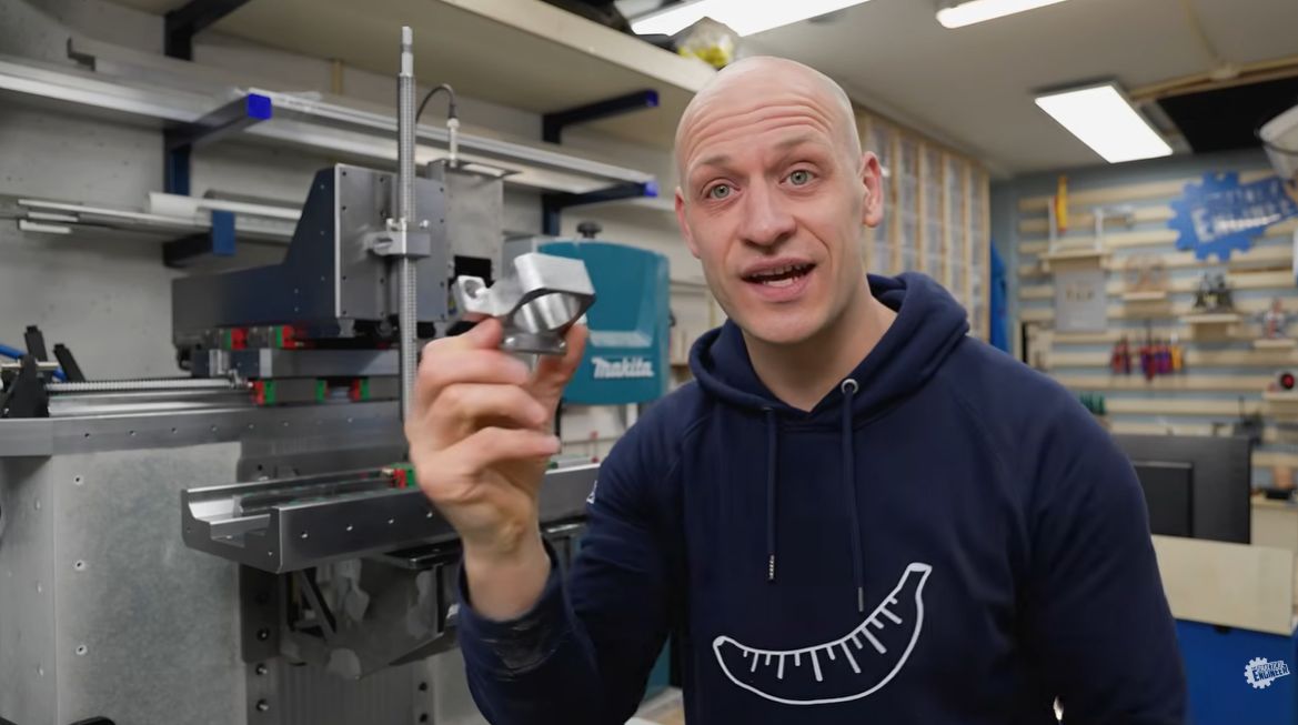
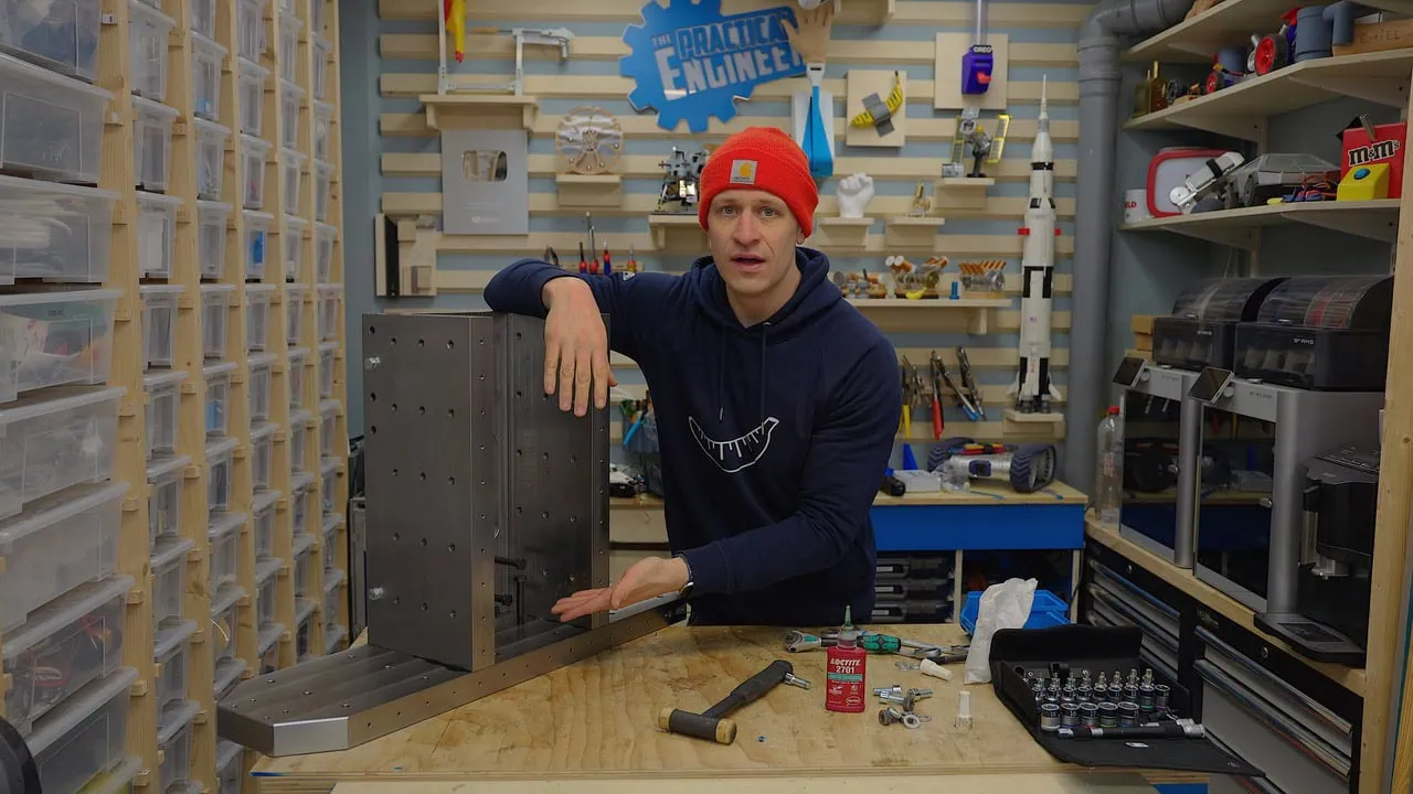
I’m Emiel, The Practical Engineer. If you’ve been following my 5-axis CNC build, you’ll know the project recently hit a significant milestone: a 400 kg, high-rigidity frame built from steel and concrete. With that cured and solid, I moved on to the Z-axis assembly — only to run into a physical bottleneck that threatened to stall the entire build.
A Design That Almost Worked
I already knew the space around the Z-axis would be tight. In Fusion 360, the design looked like it should clear. But once I started physically assembling the parts, it became obvious that something was wrong: the spindle nut mount collided with the linear rail carriages.
Not by much, but enough that the entire assembly simply could not move.
Frustrating, of course. But I’ve been engineering long enough to know this is part of the process. Especially on personal projects like the ones I build for The Practical Engineer, often in the evening hours, small things sometimes slip through. The real engineering starts after that moment. How do you solve the problem without redesigning half the machine?
Why I Only Wanted to Redesign One Part
At that point, I had two options. I could redesign the larger structural parts and move the linear rails further apart, or I could try to solve the issue by redesigning only the spindle nut mount.
The rest of the machine was already correct, rigid, and expensive to remake. Redesigning everything would have cost a massive amount of time and money.
The challenge became simple: could I redesign this single part so it would fit in an extremely tight space, while still keeping it strong and rigid enough? That turned into a genuinely interesting engineering puzzle.
Back to CAD: Optimising the Geometry in Fusion 360
I went back into Autodesk Fusion and started optimising every millimetre of available space.
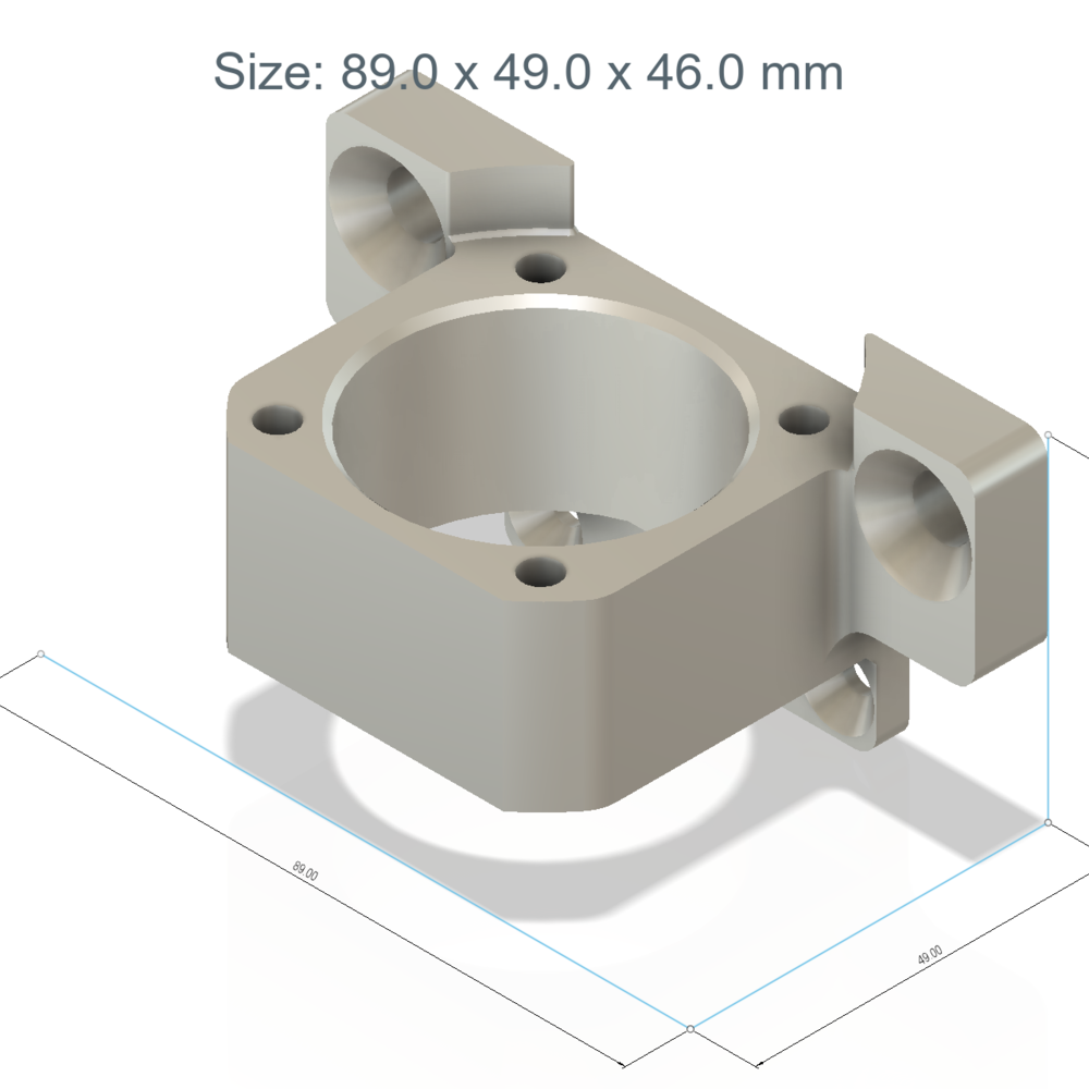
The first version of the mount already had clearance cutouts, but I had missed something important: the spindle nut, the mounting bolts, and the rail carriages all needed space in the same very small area. Once I sectioned the model in CAD, the issue became obvious.
The redesigned version became much flatter and more compact. I lowered the spindle nut position, optimised the shape around the rail blocks, and removed every bit of unnecessary material I could. In some places, the final clearance was only about 1 mm.
Tight, but enough.
Why This Part Needed to Be CNC Machined
For the new version, I chose steel and had the part CNC machined. 3D printing was not the right option here. This mount is part of the Z-axis drive system and needs to stay rigid under load. Any flex in this component would directly affect the stiffness and accuracy of the machine.
The difficult part was finding the balance between two things: keeping the part compact enough to fit, and keeping it strong enough to do its job. That balance is exactly what made this part interesting.
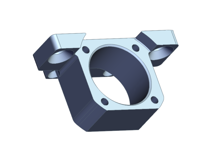
3D CAD render of the redesigned spindle nut mount design
Having the Part Manufactured by Xometry
Once the redesign was finished, I uploaded the CAD file to Xometry.
For a project like this, that kind of service is extremely useful. Some parts are either too precise, too time-consuming, or simply not realistic to make in the workshop. This spindle nut mount was one of them.
The process was straightforward. I uploaded the model, selected the material and manufacturing method, checked the price, and ordered. The part arrived in roughly six working days, which was surprisingly fast — and in this case, it really helped keep the project moving.
The Moment of Truth
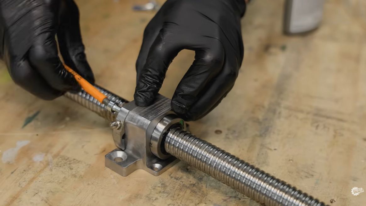
I ordered the part from Xometry and, when it arrived roughly six working days later, I installed it into the Z-axis assembly straight away.
This time, it fit.
The rail carriages cleared the mount, the spindle nut aligned correctly, and the Z-axis could finally move freely. Considering how heavy the whole assembly had become, seeing it mounted and working felt extremely satisfying. It wasn’t just that the part fitted. It meant I could finally continue with the machine.
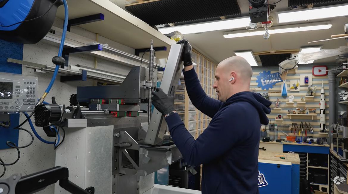
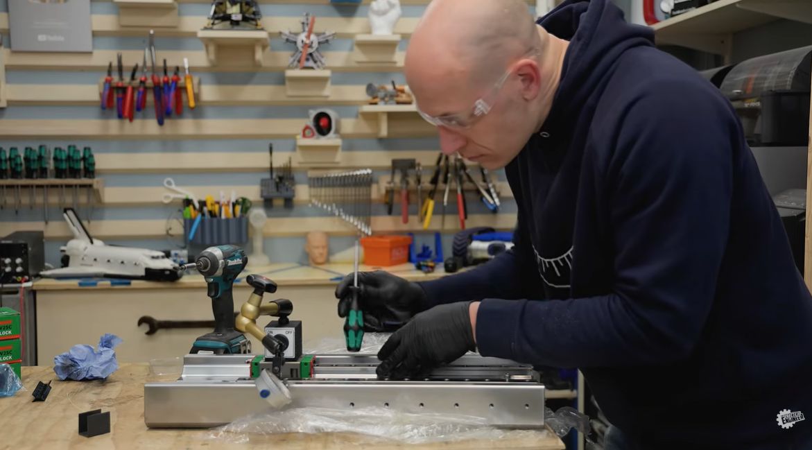
Emiel fitting the Z-axis assembly onto the full CNC machine frame
Why These Problems Are Actually Fun
As frustrating as these moments can be, this is also one of the things I enjoy most about engineering projects.
You run into a constraint. You rethink the design. You optimise the geometry. You puzzle your way through the problem until you find a solution that works. Often, the final solution is better than the original idea.
That is also why I like sharing these projects on The Practical Engineer — not only the finished machine, but also the mistakes, redesigns, and practical problem-solving that happen along the way. That is where the real engineering is. You can follow the full journey, from the booster backpack to the magnetic couplings experiment and the 5-axis CNC build, right here on Xometry Pro.
What Comes Next
Now that the Z-axis assembly is working, I can continue toward the next big milestone: getting the machine running as a functional 3-axis CNC.
After that, the plan is to use the machine to make parts for the 4th and 5th axes. Once the machine can start making parts for itself, the project enters a completely new phase — and that is the part I am really looking forward to.
From Desktop Dreams to 400kg of Steel and Concrete: Building a High-Rigidity 5-Axis CNC
Machine Building
CNC Machining
Prototyping
Read Story
In the world of custom machine building, I’ve found there is a constant tug-of-war between theoretical performance and physical reality. As "The Practical Engineer," I dedicated this project to creating a 5-axis CNC machine that prioritizes rigidity over sheer speed.
Read Story

Torx Robot: The Story Behind Accu’s Engineering and Xometry’s Precision CNC Machining
Robotics
Machine Building
CNC Machining
Prototyping
Read Story
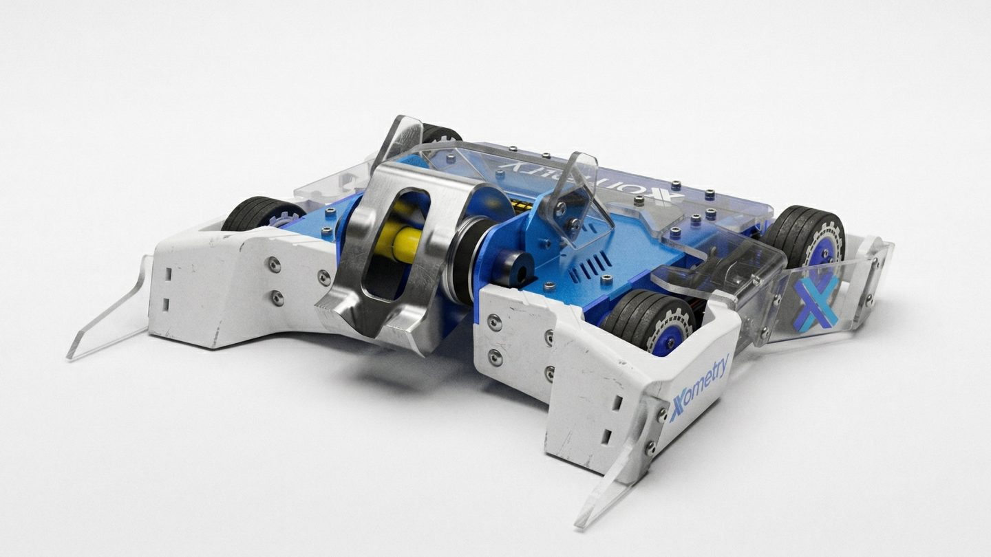
Go behind the scenes for the development of Torx: the combat robot built by Accu for FightFest 2026, with CNC machining support from Xometry. Explore the journey from the drawing board to the arena, showing how a combat robotics project takes shape, and see how Torx went on to win the official FightFest Championship trophy.
Read Story

The Rethink of 3D Printing Waste and the Next Chapter of the Desktop Filament Recycler Story
Machine Building
3D Printing
CNC Machining
Prototyping
Read Story
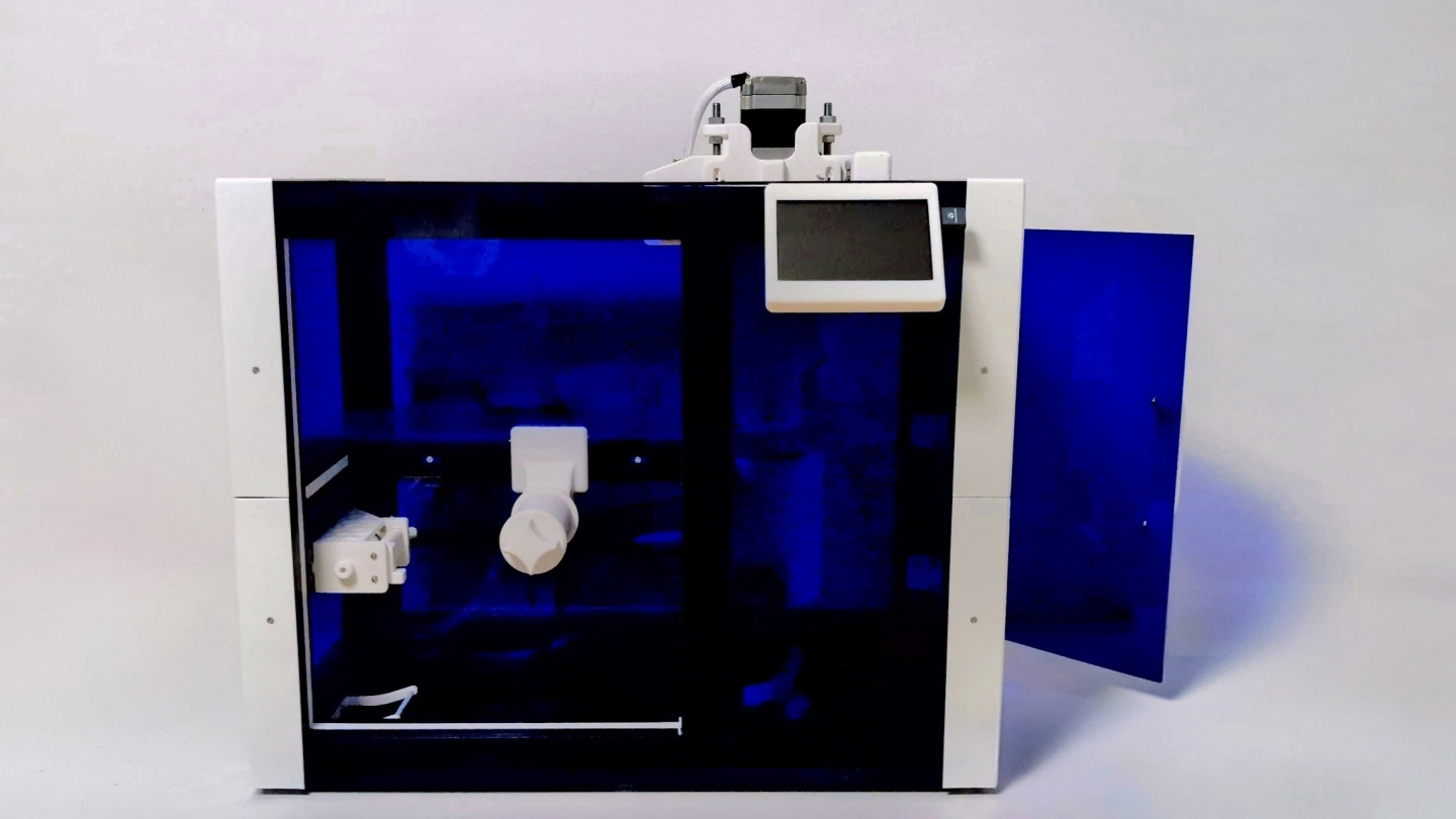
By using agile testing and redesigning a double-sided support to resolve motor deformation and calibration challenges, the TGM student team successfully turned 3D printing waste into high-quality PLA filament.
Read Story

How Zauberzeug Uses Xometry for Fast and Efficient Sourcing of High-Tech Agricultural Robot Components
Robotics
Machine Building
CNC Machining
Procurement, Prototyping
Read Story
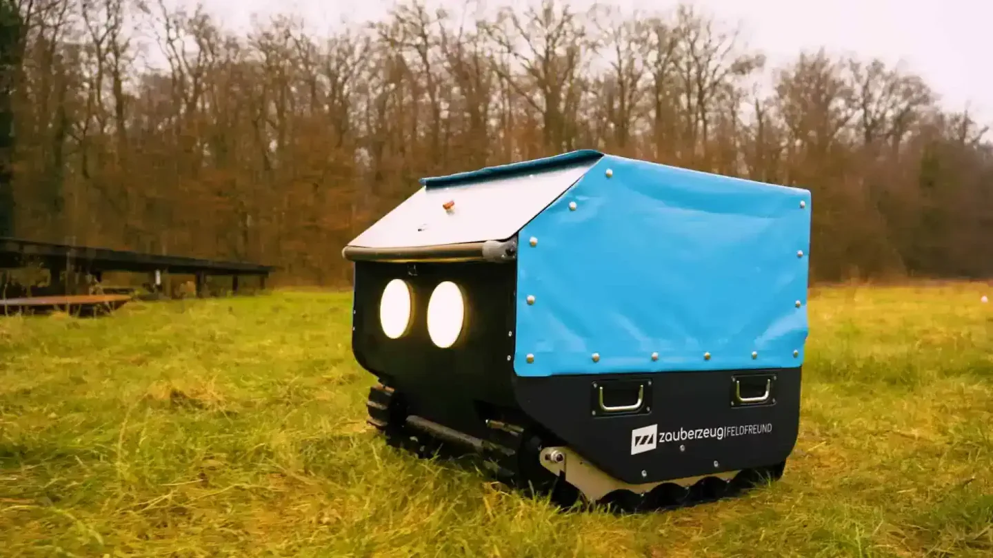
With Xometry, we have found a manufacturing partner that supports our development philosophy. The ability to quickly and precisely order small batches of parts gives us the freedom to iteratively improve our robots. This flexibility is essential to our innovation process.
Read Story


Aerospace Institute Speeds Up R&D with Xometry's On-Demand Complex Parts
Machine Building
3D Printing
CNC Machining
Prototyping
Read Story
In the past, developing non-standard devices was always complicated by the issue of tolerance matching between externally purchased standard parts and custom-machined components. Xometry's one-stop solution perfectly solved this pain point: they not only handled the complex metal 3D printing and sourcing of components but also delivered a finished product that had undergone precision assembly and adjustment. What we received was a functionally ready component that met our precision requirements. This efficient and worry-free delivery experience is exactly what R&D personnel need.
Read Story
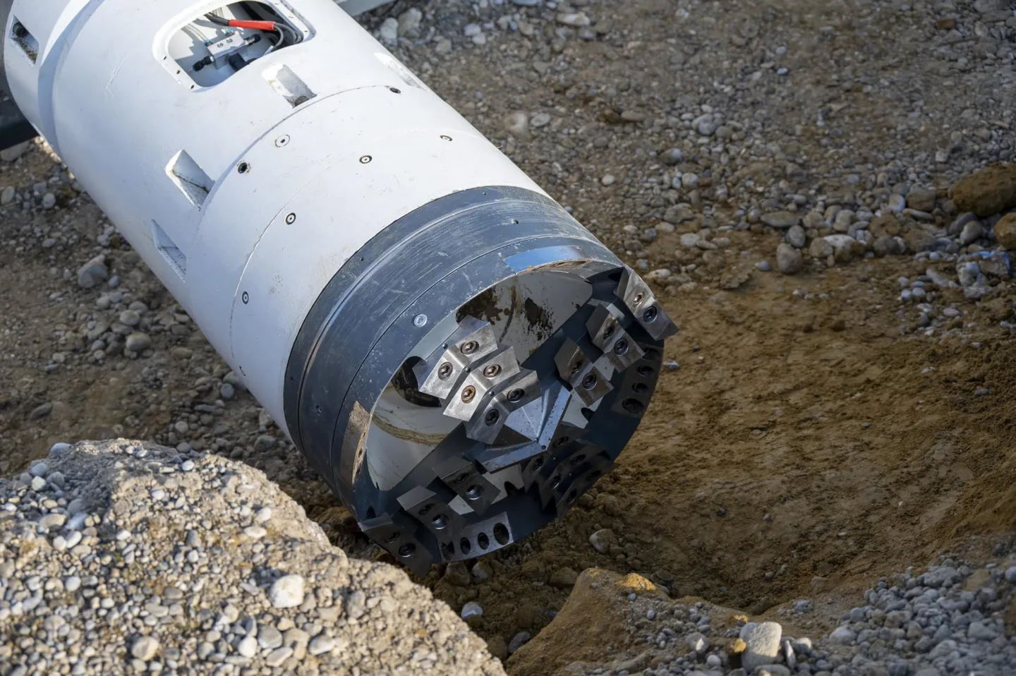
How We Set Tunneling Records and Won the Not-a-Boring Competition
Machine Building
CNC Machining
Prototyping
Read Story
The lessons we learned go far beyond mechanics. We reflect on three key takeaways: people are the ultimate success factor — both the team and its supporters; divide and conquer: breaking the project into subsystems prevents chaos and enables parallel innovation; and industry partners like Xometry are strategic enablers, not just suppliers.
Read Story
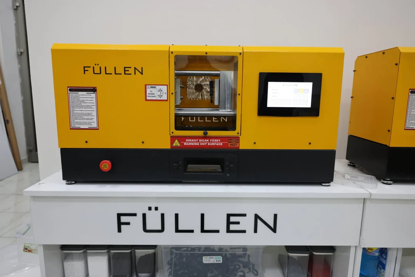

Füllen’s Desktop Plastic Injection Machine MiniMolder Manufactured with Xometry
Machine Building
CNC Machining
High-Volume Manufacturing
Read Story
We make the design, upload it to the Xometry Instant Quoting Engine. We see the price and delivery time immediately. Previously, we had to contact four or five different places separately. Now, we receive ready-to-assemble parts from a single channel.
Read Story
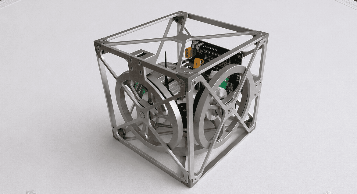
A Cube That Doesn’t Fall Over: The Making of a Self-Balancing Gyroscopic Cube
Machine Building
Sheet Metal
Prototyping
Read Story
The HTL team from Austria overcame mass distribution and precision challenges to successfully build Cubli, a self-balancing cube powered by reaction wheels and control algorithms.
Read Story
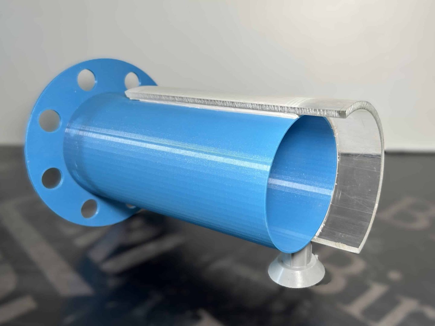
A New Era of Sealing for Wastewater Infrastructure: Xometry Supports Development of Universal Fittings for Pressure Pipelines
Machine Building
3D Printing
Prototyping
Read Story
Our development process begins with extensive brainstorming of potential shapes and sealing methods. 3D printing plays a key role at this stage, allowing us to quickly test different designs before determining the final production materials. Since the final materials are too costly and time-consuming for early prototype stages, we focus on creating small-scale test models in-house, then produce large prototypes through Xometry to ensure convenience and accuracy.
Read Story

Recreating the Barentsz Clock: A Blend of Tradition and Modern Manufacturing
Machine Building
3D Printing
Prototyping
Read Story
The Horological Society continuously balances its respect for traditional craftsmanship with an openness to modern innovation. One such innovation is the use of 3D printing, which has become an invaluable tool for prototyping clock components in plastic. By sourcing high-quality 3D-printed parts through Xometry, we should be able to test designs efficiently before committing to metal production. This approach allows us to refine intricate mechanisms like gear assemblies with minimal waste and cost.
Read Story
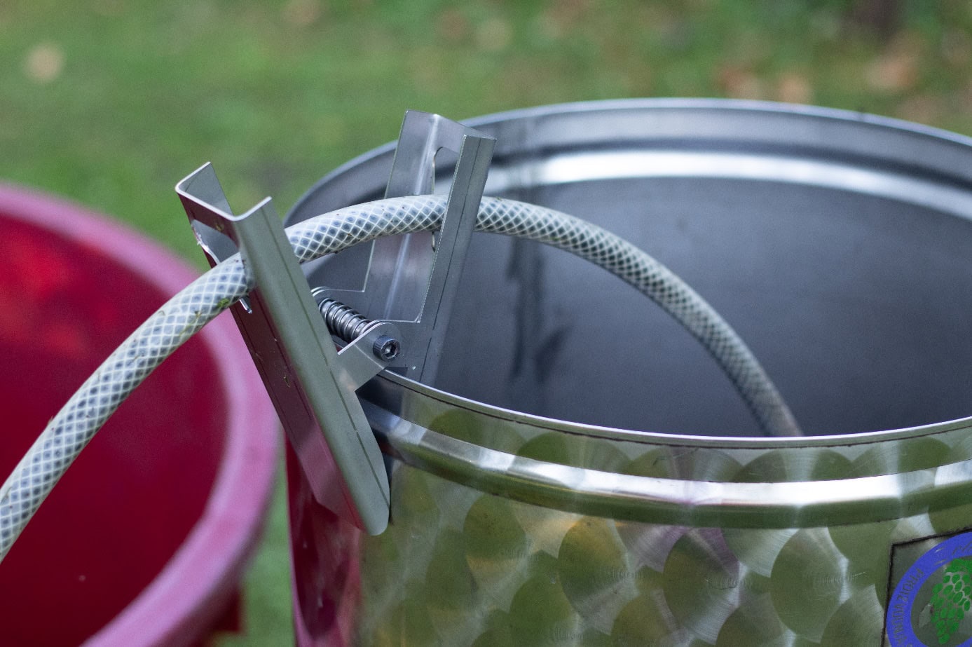

Designing a Hose Clip for the Beverage Industry: From Faculty Project to First Business Venture
Machine Building
Sheet Metal
Prototyping
Read Story
A student team from University of Maribor developed a stainless steel hose clip for the food and beverage industry, targeting wine and beer fermentation vessels. With Xometry's laser cutting service, they produced 1.5mm thick stainless steel sheet parts featuring elongated teardrop-shaped holes that pinch hoses at two points. The 80 × 45 × 170 mm design requires no lubrication, is food-safe, and grips vessel flanges securely without screws.
Read Story
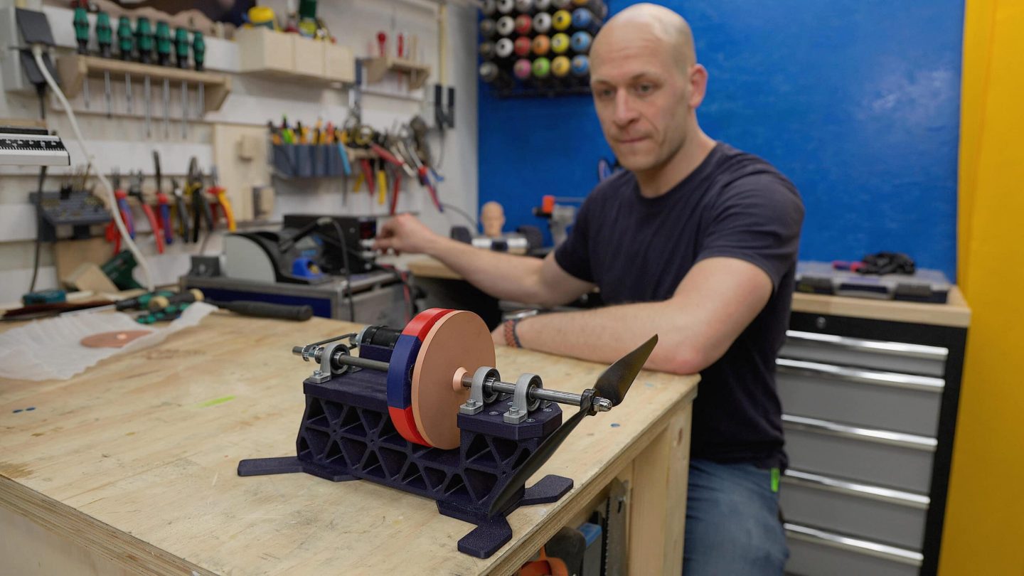

Exploring Magnetic Couplings: No Gears, No Belts, Just Magnets
Machine Building
3D Printing
Sheet Metal
R&D
Read Story
Emiel, an aerospace engineering graduate and creator of "The Practical Engineer" YouTube channel, built two magnetic coupling prototypes: magnet-to-magnet and magnet-to-copper using eddy currents. With Xometry's laser cutting service, he sourced copper plates of 3mm and 6mm thickness, discovering that the copper version enables smooth, self-regulating, non-contact torque transfer with 8mm gap capability.
Read Story