Designs for CNC machining could be improved just by following a few tips. CAD software packages have provided easier ways to produce engineering designs, however designing for CNC machining still requires much precision and accuracy to produce quality designs. This article covers 10 ways in which you can improve your CAD designs.
1. Avoid designing excessively thin walls
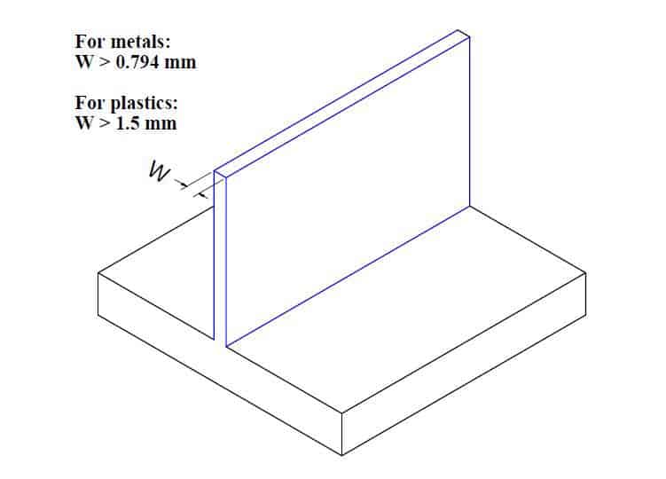
Thin walls are a requirement for certain engineering projects such as drone parts or whistles. Avoiding excessively thin walls would improve your models when designing for CNC machining. Studies have shown that wall thickness is proportional to the stiffness of the material, therefore lowering the wall thickness would also lower the stiffness of the material hence reducing achievable accuracy as a result of inevitable vibrations during machining. The standard minimum thickness for walls is 0.794 mm for metals and 1.5 mm for plastics.
In cases where designing such thin walls are necessary, employing other manufacturing processes like sheet metal fabrication is advisable and economical.
2. Avoid designing features that cannot be CNC machined
Not all features can be machined. Similar to thin walls, unnecessary features would only make designs difficult to machine. Knowing the machine’s capabilities is often an advantage when designing for CNC machining, as this would help you design features producible by the machine.
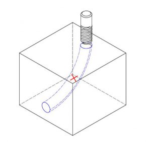
An example of an impossible to machine feature which cannot be produced with CNC mills, lathes or drills is “curved holes”. However, if this feature, as well as other impossible to machine features, are necessary for your design, electrical discharge machining (EDM) may be used.
3. Avoid excessive use of tolerances
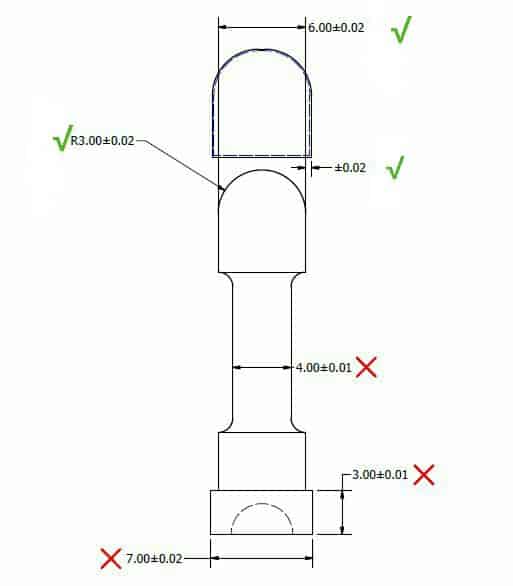
Designers are expected to tolerance dimensions where necessary. But it is important to note that excessive tolerancing would only increase machining time and cost. Different CNC machines have different tolerance standards, therefore if your dimensions have no tolerancing, the machine would use its standard tolerance for such dimensions. To save time and cost, tight tolerances should only be specified when necessary as they are. It is also important to maintain homogeneous tolerancing as this would reduce machining time.
4. Avoid designing unnecessary aesthetic features
As stated in the aforementioned ways to improve CAD designs, some features are only aesthetic and cannot be efficiently machined. Before removing parts for just looks, it is important to consider the amount of material to be removed and the process to be used in doing this. As a designer, you should always consider questions like “what process would this feature require?” or “is it a 5-axis or a 3-axis machining process?”. You can improve your design by paying attention to the accuracy of necessary features rather than aesthetics seeing as post-machining processes such as electro-polishing could be used to achieve aesthetics.
5. Design cavities with accurate depth-to-width ratios
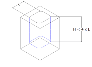
You can improve your design by taking into consideration, depth to width ratio of cavities when designing cavities. Too deep cavities would result in the tool hanging, tool deflection, difficulty in chip evacuation, and tool fracture.
Cavities higher than six times the tool diameter are considered deep, and should have a maximum depth of four times the width of the cavity. For example, a 15 mm wide cavity should not be more than 60 mm deep.
6. Add radii when designing internal edges
Designing internal edges can be stressful on the machining tool considering its shape. Since most cutting tools are cylindrical and cannot machine sharp internal edges, it is important to add radii to internal edges in your design. To avoid wear and tear of the tool, it is necessary to design internal edges that would not stress the tool more than necessary. In order to achieve this, a good rule of thumb is to add a radius of 130% of the milling tool radius. If your milling tool has a radius of 5 mm, it is recommended that you add a radius of 6.5 mm to all your internal angles. This additional radius would reduce stress on the tool and increase cutting speed.
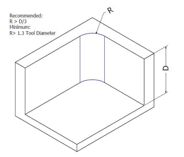
If 90 degrees internal edges are your design requirements, you can add an undercut as opposed to reducing the edge radius.
7. Limit thread length
It is common engineering knowledge that strong thread connections take place in the first few threads. Therefore, very long threads are sometimes completely unnecessary. When designing tapped holes, you can improve your design by designing just sufficiently long thread lengths. A thread longer than 3 times the hole diameter is unnecessary.
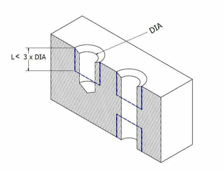
However, when designing for blind holes, it is advisable to add an unthreaded length at the bottom of the hole and when a CNC threading tool is used, the hole can be fully threaded.
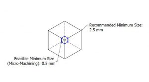
8. Avoid designing too small features
Most CNC machines have a minimum tool diameter of 2.5mm, therefore any feature smaller than 2.5mm would be difficult to machine. Too small features would require a special tool and this would increase machine costs and time. Therefore too small features should be avoided except when necessary.
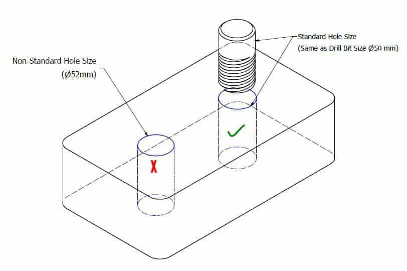
9. Design holes with standard sizes
Standard sized holes are milled using standard drill bit sizes. This saves machine time and cost as holes not designed to standard would require an end mill tool.
In the case of non-standard holes, the rule of thumb for depth of cavity must be applied, which is the depth must be four times the diameter of the cavity.
10. Avoid unnecessary text and lettering
Designing parts with text and lettering is unnecessary. Any required texts can be painted on the surface of the machined part during finishing. Designing texts for machining would only increase machine time and cost.
However, if text and lettering are design requirements, the following rules should be followed:
- Engraved texts should be used as less material is removed in this case.
- If your design software does not have a custom lettering font, then the San Serif font with 20 points is recommended. This is because this font does not have extra lines (serif) at the end of each lettering stroke. These extra strokes increase machining cost. Also, size 20 is recommended because sizes smaller than this are considered small feature which are more difficult and costly to machine.
推荐阅读:CNC加工数控车床