1. Home
  2. »
  3. 博客
  4. »
  5. 上手指南
  6. »
  7. CNC加工工艺
  8. »
  9. CAD Designs for CNC machining: overview

CAD Designs for CNC machining: overview

This article explains what is CAD, what are the typical formats of such designs and how they are applied in CNC machining

What is CAD?

CAD (Computer-aided design) is the utilisation of computers to assist in the modelling, alteration, analysis, and optimization of a design. It involves creating computer models defined by geometric and numeric parameters. These models are usually displayed as two or three-dimensional depiction of a part or an assembly. CAD systems allow designers to not only view objects under a variety of representations such as algebraic and parametric curves and surfaces but also allows you to test these objects by simulating real-world scenarios. For example, after you design a bridge using Solidworks, you can test the behaviour of the bridge under loading, using Solidworks’ simulation features. All these are achieved using a variety of software packages. The output is usually in the form of electronic files for 3D printing, machining, and other manufacturing processes.

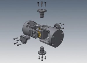
3D CAD model of an exploded universal joint
Figure 1: 3D CAD model of an exploded universal joint

With far-reaching technological advancements in the field of manufacturing, computer-aided design has become an indispensable aspect of manufacturing. The parts manufactured using CAD files are applied in a number of industries that require high precision and complex elements such as automotive, shipbuilding, aerospace, and architecture. Its use in designing electronic systems is known as computer-aided drafting (CAD) or electronic design automation (EDA). CAD applied to mechanical design is known as mechanical design automation (MDA). It is the process of creating a technical design using a computer software package.

CAD software packages for mechanical design use vector-based graphics or raster graphics to portray the features of traditional drafting. CAD, however, involves far more than shapes alone. Similar to the manual drafting of engineering and technical drawings, the output of CAD processes must convey information such as processes, materials, tolerances, and dimensions.

What are typical CAD formats and what is the basic difference between them?

Similar to most software packages and electronic files, CAD software packages have unique file formats and extensions. CAD files may contain 2D or 3D designs. There are numerous CAD formats existing today. However, .DWG, .DXF, .DGN, .STL and .STEP are the most common.

.DWG

Derived from the word, drawing, DWG is a binary file format used for storing 2D and 3D design data and metadata. It was developed by Autodesk and is supported natively in many CAD packages.  You may view DWG files on Windows using Autodesk’s free DWG TrueView program. Any third-party application that supports the DWG file format can also open DWG files.

.DXF

DXF fully known as Drawing exchange format is an exchange format for the content of CAD drawing (DWG). DXF files are similar to .DWG files, but are more compatible with other programs. This file format was created as a universal format so that other programs may easily open AutoCAD documents.

.DGN

DGN (design) files are drawings created using CAD construction software packages, such as Intergraph Interactive Graphics Design System and MicroStation. A DGN file may be saved in either the DGN standard format or the Intergraph Standard File Format (ISFF).

.STL

STL format is a file format derived from stereolithography CAD software. Stereolithography is a rapid 3D printing prototyping technology employed in the production of prototypes, models, etc. An STL file contains a three-dimensional design which serves as the main model used in manufacturing numerous prototypes.

.STEP

STEP stands for “standard for the exchange of product model data”. STEP is an ISO standard CAD file format that solves the problem of interchangeability of files between CAD programs. This file format is used to share models between users having different CAD packages.

CAD and CNC machining

CNC machines, fully known as Computer Numerically Controlled machines are electro-mechanical devices that can navigate tools around different numbers of axes usually (three or five), with high precision following instructions from a computer program. CNC machining is one of many ways in which engineers manufacture machine parts from a computer-designed file. This approach is known as subtractive manufacturing. Another manufacturing approach is 3D printing, which is called an additive manufacturing process.

Before CAD, CNC machines operated using a data storage system known as punched tapes. The codes were manually punched onto the punched tape cards and fed into the machine.

CNC machines rely on digital instructions referred to as G-CODE, which is a coded guideline on how the machine tool will move in 3D space. G-CODE can be written manually, but it would be tedious and prone to mistakes. G-CODE is written by CAM (computer aided manufacturing).

CAM is responsible for converting the model designed in CAD to G-CODE which the CNC machine understands. CNC machine then uses the G-CODE generated by the CAM from CAD file as instructions for its tool path.

In a nutshell, CAD creates the design geometry; CAM designs the tool path while CNC uses the output from the CAM to actually make the part. This is the relationship between CAD, CAM, and CNC machining.

推荐阅读:CNC加工技术