惠普尼龙多流射熔融成型(MJF)是一种专有的粉末熔融3D打印技术,由惠普公司研发。该技术能够以高精度打印极为复杂的部件。为了充分发挥惠普尼龙多流射熔融成型(MJF)的功能和精度,您的3D模型需按照建议进行设计。在本概述中,您将找到惠普公司的设计建议。
尺寸限制
虽然最大建造体积为380 x 284 x 380毫米,但推荐最大尺寸为356 x 280 x 356毫米。
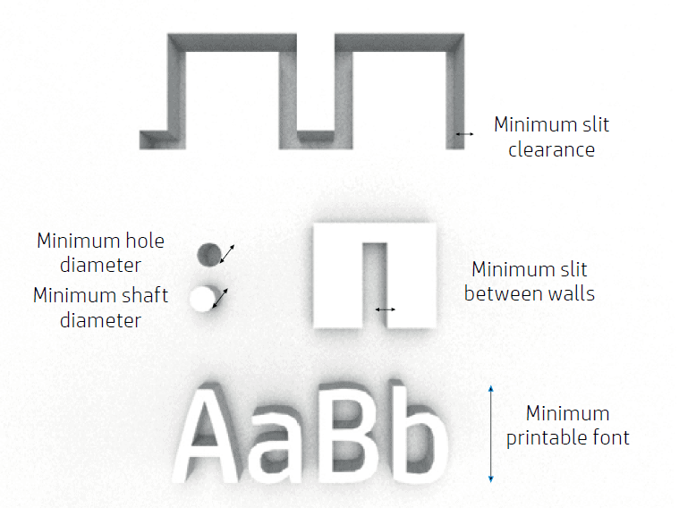
惠普尼龙多流射熔融成型(MJF)技术能够打印非常小的部件,但也有限制。不同X、Y和Z平面特征的最小可打印尺寸如下:
- 1毫米厚度处的孔直径:0.5毫米
- 高度为10毫米处的轴直径:0.5毫米
- 浮雕和雕刻的字体大小:6磅
- 1毫米厚度处的最小间隙:0.5毫米
- 壁间的最小缝隙:0.5毫米
浮雕和雕刻细节
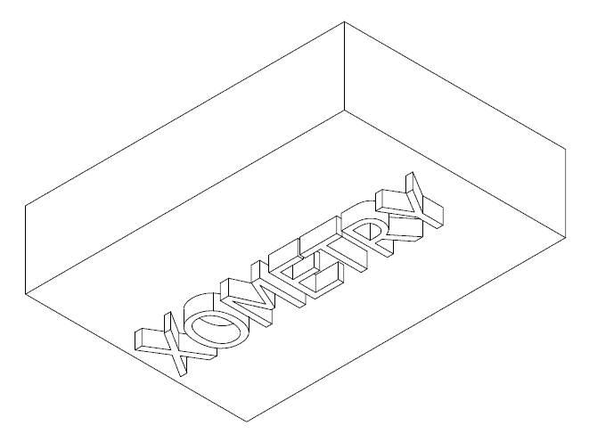
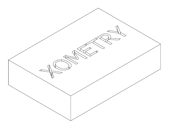
使用惠普尼龙多流射熔融成型(MJF)技术,您可以打印高分辨率的文字、数字和图形。部件中包含的任何图案应具有至少1毫米的最小深度或高度。这是为了确保可见性,并在后处理过程中防止图案磨损。
通过倒置的方式进行浮雕可以达到最佳分辨率,而雕刻则应朝上进行。
公差
惠普尼龙多流射熔融成型(MJF)技术可以在经过喷砂处理后,实现对于100毫米内的部件尺寸精度达到±0.2毫米,超过100毫米的部分则为0.2%。
固体部件与结构填充
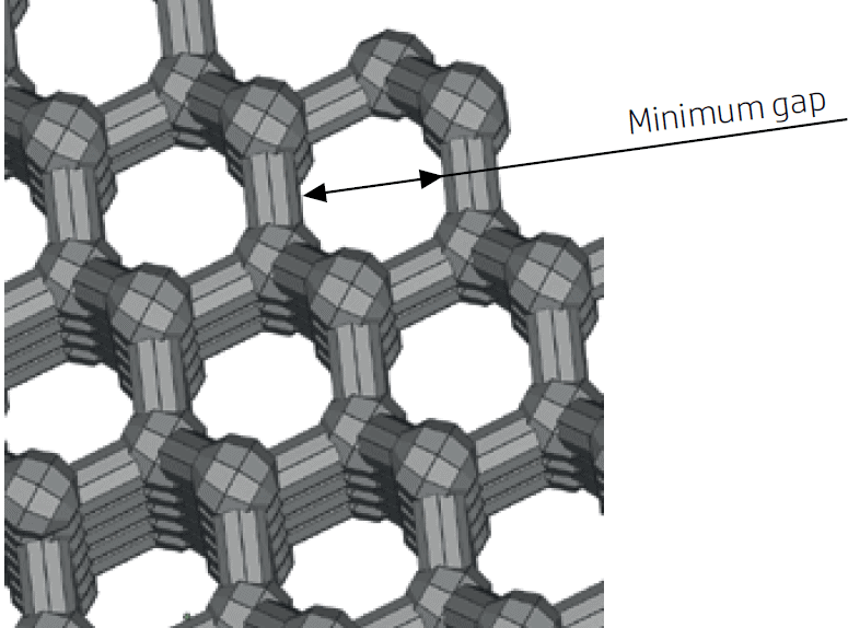
使用惠普尼龙多流射熔融成型(MJF)技术,可以打印小型的晶格结构,以及拓扑优化的生成设计。这些设计有助于减少材料使用量和部件重量。这意味着在对重量敏感的应用中,可以实现显著的成本节约。
在晶格结构中,建议最小间隙尺寸为1毫米,这样做是为了便于清除部件内部的残留材料。
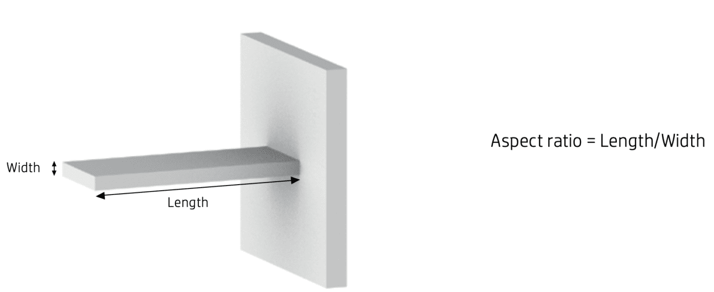
壁与悬臂结构
悬臂结构的最小壁厚取决于其长宽比,即长度与宽度的比值。对于宽度小于1毫米的悬臂结构,其长宽比应小于1。
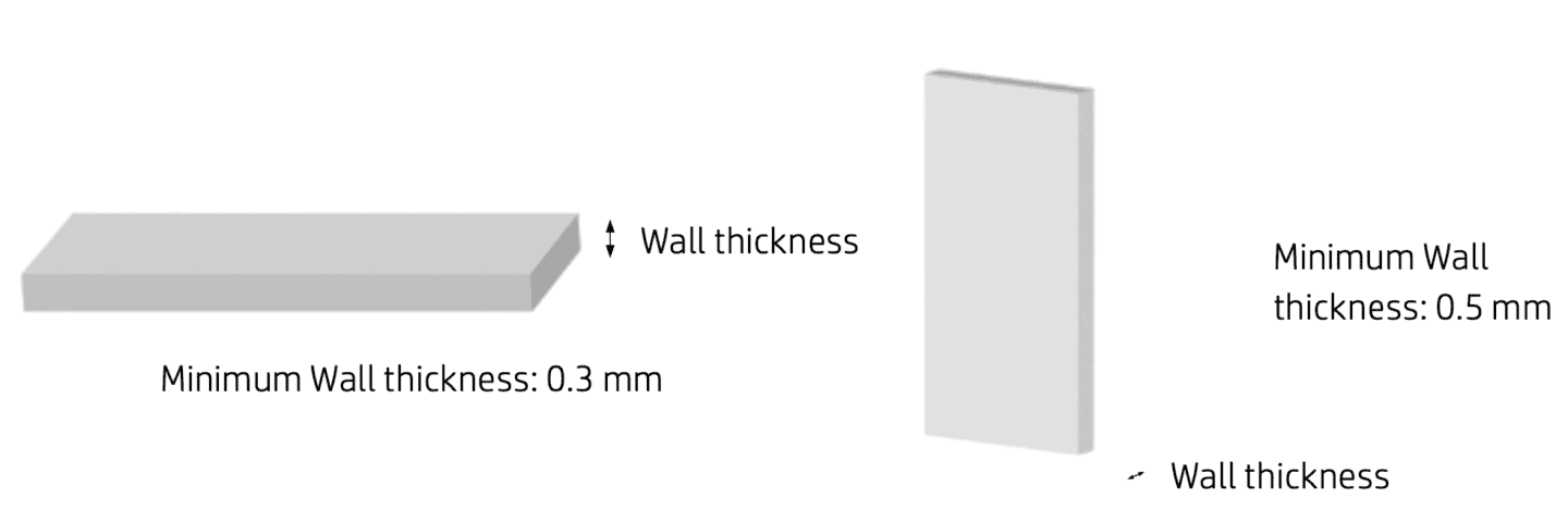
在XY平面上,短壁的推荐最小厚度为0.3毫米,而在Z轴平面上短壁的最小厚度为0.4毫米。如果高长宽比至关重要,可以增加壁厚或者添加肋条或圆角来加固部件。需要注意的是,过厚的壁容易积聚热量并导致局部收缩。
组装件
由于其高精度,惠普尼龙多流射熔融成型(MJF)技术可以打印出具备完全功能的组装件。需要一起打印的组装部件之间的最小间隙应为0.7毫米,以防止组件融合形成单个实心部件。对于壁厚超过50毫米的部件,这个值应适当增加。
对于打印后需要组装的部件,需要至少0.4毫米的间隙,每个配合部件的间隙应为0.2毫米。
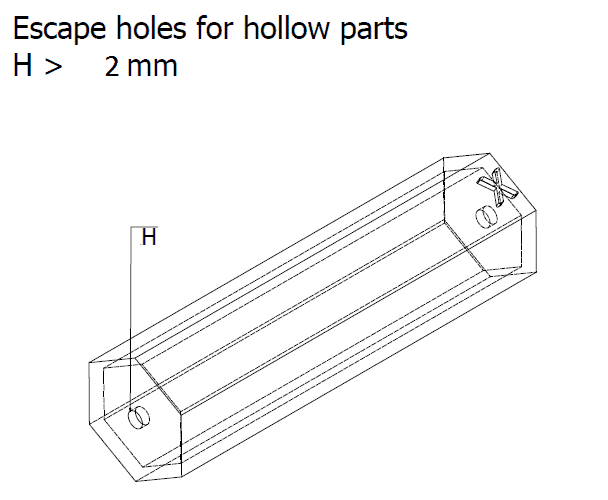
空心封闭部件
您可以打印空心封闭实体以减少部件的重量和材料使用量。这类部件在打印后需要至少两个排泄孔,以排出任何残留的材料。推荐的孔径大小为2毫米。
胶粘接线
过大以至于无法一次打印的部件可以分割成不同的部分,分别单独打印,然后再粘合在一起。如果您打算采用这种方法,建议在需要粘合的部位设计联锁特征,以帮助部件正确粘合。应额外增加0.1至0.2毫米的胶粘接空间,以及组装部件的最小间隙。
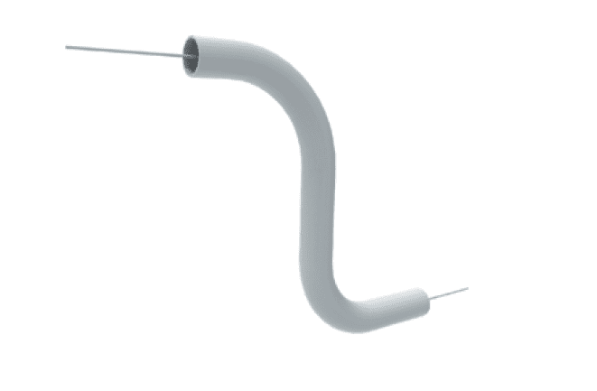
导管
设计打印导管时,考虑添加一个条带。打印完成后,可以简单地拉出这条条带,以清除残留的粉末,便于更轻松地清洁。
部件定位
设计时应选择的定位取决于多个因素。以下是其中一些因素:
- 层叠:由于惠普尼龙多流射熔融成型(MJF)技术打印的逐层堆叠特性,可能会出现层叠现象,即可以检测到构成部件的层。为了避免在曲面或倾斜表面出现层叠现象,最好避免将这些表面放置在小于一定角度的位置,具体取决于部件的厚度。
- 精度:需要高精度的特征应该放置在XY平面,因为这个平面上的特征精度更高。
- 翘曲:为了最小化翘曲,长平坦表面应该与水平平面对齐。这样的表面应该设计在建构槽尽可能低的位置。
- 表面光滑度:需要特别光滑表面的曲面应该倒置,而锋利的表面则应该朝上放置。
- 负载:需要承载负载的特征,如夹具或销钉,应尽可能设计为水平放置。在XY平面上实现最佳的机械性能。
您想要将您的设计进行3D打印吗?只需将它们上传至Xometry择幂科技实时报价引擎,即可在几秒钟内获得制造性反馈、报价单和生产周期!