CNC milling is one of the most widely used machining processes. This article explains the process of CNC milling, its advantages, limitations, and everything you need to know when you order CNC milled parts.
Feel free to get an instant quote for CNC milled parts, using our online platform.
The industrial revolution in the 18th century marked the beginning of the alliance between man and machine, with the aim of manufacturing. Before this period, the main method of manufacturing was casting. This, alongside other methods available at the time, were manual, tedious, and error-prone. Today, however, with advancements in digital technology, manufacturing processes that can produce very complex parts with high speed and accuracy now exist. One of these is CNC (Computer Numerical Control) milling.
What is CNC milling?
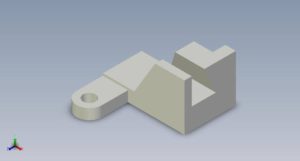
CNC milling is a subtractive manufacturing process in which computer-controlled cutting tools progressively remove material from a workpiece in order to create a desired shape or object. This process is achieved using machines known as CNC milling machines or CNC mills. It is the most widely-used of the mechanical machining processes, others being CNC turning and CNC drilling.
Parts of a CNC milling machine
To better understand the process of CNC milling, it is necessary to know the parts of a CNC mill. Parts of different milling machines differ by manufacturer, type, and capacity. However, there are parts that are fundamental to every CNC milling machine:
- Spindle: The spindle holds the cutting tool in place.
- Control panel: The operator uses this component to control the machine. This is where the computer interface is located..
- Column: The Column is a the main frame and support of the machine. It holds other components in place
- Saddle: The saddle is attached to the column of the machine. It supports the worktable.
- Worktable: The worktable is located on top of the saddle. It is where the operator places the workpiece and using a work holding device.
- Base: The base is what provides support for the whole machine on the ground.
How CNC milling works
Before the incorporation of CNC, control in milling machines was carried out manually. This gave a lot of room for error. The end product was in the mind or view of the machinist, similar to the way an artist paints a picture. With the inclusion of CNC however, milling became a highly precise and accurate process, involving some steps. There are four sequential steps involved in creating a CNC milled part:
- Designing a 3D model
- Converting the model to machine code
- Setting up the milling machine
- Actual milling
Designing a 3D model
The first step in the CNC milling process is designing a CAD (Computer-Aided Design) model of the part to be milled. This is carried out using CAD programs available for the purpose. Any feature that is to be a part of the final product must be indicated in the design. There are some standards and guidelines every designer should follow to properly design for CNC milling, which we have compiled.
Converting from CAD to G-Code
CNC milling machines do not understand CAD files in their native format. Instead, they depend on digital instructions known as G-Code which instructs them on how to move in 3D space. It is, therefore, necessary to convert CAD models into G-Code. This is where computer aided manufacturing (CAM) programs come in. After completing a CAD model, the designer exports it to a CAM-programme which reads it and converts it to the corresponding G-Code.
Setting up the CNC milling machine
Next is the machine setup. Before running the CNC programme, the operator needs to set up the CNC milling machine by attaching the workpiece to the mill's work surface; affixing the appropriate cutting tool to the mill's spindle; and preparing any necessary cutting fluid.
Execution of actual milling
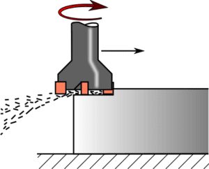
After setting up the machine, the operator initiates the milling process through the machine interface. The machine begins the actual milling by rotating the cutting tool around its axis at a very high speed of up to thousands of RPM (revolutions per minute). Depending on the nature of the milling machine, cutting action on the workpiece is achieved by one of the following movements:
- The cutting tool moves across a stationary workpiece
- The workpiece feeds into the stationary, rotating cutting tool
- Both the workpiece and the cutting tool move relative to each other
One of the following continues intermittently, making small cuts at a time until the machine produces the desired object. As the tool comes in contact with the workpiece, its cutting edges repeatedly dig into and exit the surface of the workpiece, effectively shaving off chips from the workpiece through shear force.
CNC milling terminology
Certain terms used in CNC milling may mean other things in other contexts. An understanding of these terms would help you understand your CNC machinist or designer better.
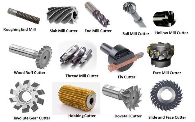
Cutting tool
The cutting tool is a detachable component of CNC mills that carry out cutting action. Cutting tools for CNC milling usually have multiple cutting points. This is because, in milling processes, the tool moves perpendicular to its axis of rotation. There are various types of cutting tools that vary by material, form, number of flutes, and placement of cutting edges. The tool selected for a milling process is dependent on the material to be milled.
Speed
Speed in CNC milling refers to the speed at which the cutting tool rotates. It is measured in revolutions per minute (RPM). Speed can be programmed and it depends on the material to be milled. For example, you can mill aluminium at much higher speeds than Steel.
Feed
This is the distance the workpiece or cutting tool moves, per revolution of the tool. Like speed, you can also programme feed. Feed also depends on the material you want to mill.
Depth of cut
Depth of cut is the distance the cutting tool moves into the surface of the workpiece. The material also determines this parameter.
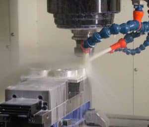
Cutting fluids
Because milling is typically a high-speed process, it usually generates a lot of heat as a result of friction between the workpiece and cutting tool. This makes it necessary to cool them down using substances known as cutting fluids.
Common CNC milling operations
There are numerous milling operations which CNC mills can carry out, depending on the type of cutting tool and the machine configuration. The four primary CNC milling operations are:
Face milling
In face milling, the cutting tool's axis of rotation is perpendicular to the workpiece surface. This operation creates flat surfaces and requires end milling cutters which have cutting edges at their tip.
Plain milling
The cutting tool for plain milling has cutting edges along its entire cutting circumference. Its axis of rotation is parallel to the workpiece surface. Plain milling produces features like pockets, slots, and cavities.
Angular milling
In angular milling, the axes of rotation of the cutting tools are at an angle to the surface of the workpiece. They are known as single-angle milling cutters. Angular milling produces features like dovetails, chamfers, grooves, etc.
Form milling
Form milling involves the production of irregular surfaces, contours, semi-circular cavities, beads, and curved surfaces. This operation employs cutting tools such as fly cutters and formed milling cutters.
Other milling operations include
- Gear cutting which is the production of gear teeth using gear cutters.
- Gang milling, in which two or more cutters simultaneously perform the same or different operations on a single work piece. It is the fastest milling operation.
- Straddle milling which employs two cutters to simultaneously mill parallel surfaces of a workpiece in a single cut.
Types of CNC mills
CNC milling machines can be classified according to the orientation of the spindle as vertical and horizontal mills. Before selecting between these two types of mills for a milling project, an operator must consider the demands of the project such as the shape and size of the part, and the number of surfaces to be milled. For example, while vertical mills provide more versatile machining options, horizontal mills are better for heavy and long workpieces.
Another major classification of CNC milling machines is according to the number of axis and axis configuration. In CNC milling, axis refers to the direction of movement of a workpiece or cutting tool. In our network, we carry out multi-axis milling operations including 3-axis, 4-axis, and 5-axis milling. These allow us to quickly and accurately produce parts from your designs ranging from simple shapes to complex geometries. 3-axis and 5-axis CNC mills are the most popular types of CNC milling machines.
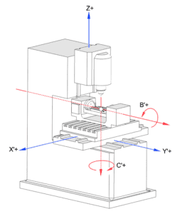
3-axis CNC mills
The cutting tool or workpiece in 3-axis CNC milling machines has three degrees of freedom. This means they can move in three linear directions; X-axis (left and right), Y-axis (back and forth) and Z-axis (up and down). In order to enable the cutting tool to reach certain areas of the work-piece, the workpiece has to be manually repositioned.
Benefits of 3-axis CNC milling
- The process is easy to program and can produce parts with simple geometry, with high accuracy.
- It has high production capacities.
- The cost of machining per part is relatively low.
- 3-axis CNC mills are less expensive than their 5-axis counterparts.
Limitations of 3-axis CNC milling
- For certain processes which require more cutting tool access, the need to constantly reposition the work-piece lowers accuracy.
- Tool cannot access to certain areas of the work-piece.
- Complex geometry and designs are more difficult to accomplish using 3-axis CNC milling machines than using 5-axis CNC milling machines.
5-axis CNC mills
In addition to the three linear axes attainable in its 3-axis counterpart, 5-axis CNC mills have two rotary axes. In most milling machine configurations, the cutting tool can only move along three linear axes. The workpiece carries out the remaining two rotary movements, thereby giving the cutting tool access to another area.
5-axis CNC mills can further be classified as indexed and continuous. In indexed 5-axis mill, the cutting tool has to momentarily stop moving as the workpiece rotates. In continuous 5-axis mills however, there's no need for the cutting tool to stop. The workpiece rotates simultaneously as the cutting tool moves.
Benefits of 5-axis CNC milling
- It eliminates the need to manually reposition the work-piece.
- It produces parts with certain very complex geometry and designs with very high accuracy.
- The surface of a 5-axis CNC milled part is very smooth. Machining marks are almost absent.
Disadvantages of 5-axis CNC milling
- Cost of machining per part is 60% and 100% higher in indexed 5-axis CNC milling and continuous 5-axis CNC milling respectively, than in 3-axis milling.
- 5-axis CNC mills are bulkier and more expensive than their 3-axis counterparts.
Materials that can undergo CNC milling
Milling is a very versatile process that applies to numerous materials. When selecting a material for CNC milling, there are many factors that you should consider like cost and material properties. Material properties include tensile strength, thermal resistance, hardness, chemical resistance, and shear strength.
Likewise, the material you select determines many aspects of the milling process including the design of the part, the cutting tool, the cutting speed and feed, the cutting fluid, and the depth of cut. There are some materials that are popular for CNC milling:
Metals
Metals and metal alloys are the most frequently milled materials. This is because of their vast use across several industries. Commonly milled metals are aluminium and its alloys, the various types of steel, brass, copper, titanium, and bronze.
Plastics
Plastics come next in terms of popularity for milling. They also have desirable properties and are widely used. Polymers like ABS, PEEK, polycarbonate, and nylon are some of the plastics that regularly undergo CNC milling.
Other materials
Wood, glass, and elastomers are also suitable materials for CNC milling.
Benefits and applications of CNC milling
Some of the benefits that make CNC milling a great option for your machined parts are as follows.
Scalability
CNC milling applies to a wide range of production quantities, whether it is a one-off custom project or a small to large scale production run. Together with its repeatability and speed, CNC milling's scalability makes it excellent for either prototyping or mass production. CNC milling is excellent for large-scale production of identical units, as production costs exponentially reduce with an increase in the number of units.
Rapid turnaround time
The inclusion of CAD and CAM programme in CNC milling has greatly reduced the time taken from making an order to receiving accurately machined parts. Precision is maintained despite high speed.
Precision
CNC milling can produce parts with very high dimensional accuracy. Tolerances as tight as 0.025 mm are feasible. This high accuracy is crucial to aerospace as well as automotive industries.
Material selection
There are over 50 engineering materials that can undergo CNC milling, as long as you use the correct cutting tool and cutting speed. Whether your material is metal, plastic, wood, glass, or even rock; if you have an application for it, it most likely can be CNC milled. Also, CNC milling has very little to no effect on material properties.
Versatility
In addition to being able to produce various shapes, CNC milling can accurately machine a variety of features including, pockets, threads, chamfers, slots, cavities, etc.
Limitations of CNC milling
Cost of complex geometries
In subtractive manufacturing processes such as CNC milling, cost increases as the amount of material the machine needs to remove increases. Therefore, the cost of milling complex geometries which require a lot of material removal increases with the level of complexity.
Work holding and tool access restrictions
Securing the workpiece in place is crucial in CNC milling processes. However, this creates some restrictions as the tool cannot access the portions of the workpiece being held. In such cases, the workpiece needs to be manually repositioned. This increases machining time and also increases the possibility of errors.
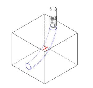
Features that cannot be milled
There certain features such as curved holes, straight internal edges, and walls thinner than 0.5 mm, that cannot be milled. While we encourage you to avoid such features when designing for CNC milling, they are sometimes necessary for a part to function. In such cases, other forms of milling may be employed.
Material wastage
When compared with formative and additive manufacturing processes, CNC milling creates a lot of waste material as chips. If you can't recycle these, they may have serious environmental and cost implications.
Industries that require CNC milling
Many industries depend on CNC milling for the production of parts. Likewise, individuals regularly need this process for their parts. In addition to its high speed and precision, the scalability and versatility of CNC milling make it almost indispensable to the following industries.
- Space
- Electrical
- Aerospace
- Automotive
- Manufacturing
- Sports
- Robotics
- Constriction
- Furniture
- Medical
- Food
- Tooling
Alternatives to CNC milling
While CNC milling is very versatile and ubiquitous, it may not be suitable for every manufacturing application. Other machining methods may prove more cost-effective and appropriate for your project. Some of these methods are as follows:
- Mechanical processes involving machine tools - Drilling and turning
- Mechanical processes without machine tools - Abrasive jet machining, ultrasonic machining, and water jet cutting.
- Non-mechanical processes - Electrical discharge machining (EDM), plasma cutting, electrochemical deburring, and laser cutting.