Tolerances in CNC machining are defined as the acceptable range a parameter can deviate from its intended value. A parameter may be a measurable physical property such as temperature, humidity, noise levels, stress, solar irradiance and speed, or a physical dimension, for example, the definition of space.
It specifies the permissible limits of variation before a value is deemed out of place. In engineering, tolerance can be viewed as the permissible degree of error. Tolerances typically have an upper limit which is the maximum allowable positive deviation, and a lower limit which is the maximum allowable negative deviation.
Tolerances used in CNC machining
The term tolerance is used in two different contexts in regards to CNC machining: in terms of CNC machines and in terms of design for CNC machining.
Tolerance in the context of CNC machines is the degree of dimensional accuracy a machine can achieve when machining a part. CNC machines are highly accurate with some machines being able to produce parts to an accuracy of ± 0.0025mm. That's the size of a quarter of a human hair. However, the tolerances of different CNC machines vary and are usually specified by the manufacturer, for example, 0.02mm is a typical average tolerance. CNC machining service providers also specify the tolerance of their machines to customers.
In design and manufacturing, tolerance is the acceptable range of variation of the dimensions of a part, that will still allow full functionality of the part. Tolerances are determined by the designer and are based on the function, fit, and form of the part. They are especially crucial for components that mate or interfere with other components. For example, the parts for an electric engine would need to have a higher tolerance compared to a door handle. This is because the former has a lot of features that mate with other components. A tolerance is represented by a numeric call-out written beside the dimension to which it applies.
There are different types of tolerance including limit tolerances, unilateral tolerances, bilateral tolerance, and a system of tolerances known as geometric dimensioning and tolerancing (GD&T).
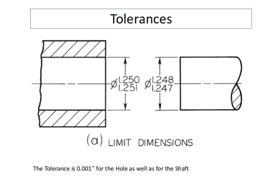
Limit tolerances
Limit tolerances are two-dimensional values that specify the acceptable range of a dimension. The upper limit specifies the maximum acceptable dimension while the lower limit specifies the minimum acceptable dimension. Any value in between these two is acceptable. 0.55 - 0.65 mm is an example of a limit tolerance, with 0.55 mm as the upper limit and 0.65 as the lower limit.
Unilateral tolerances
A unilateral tolerance is one in which only one direction of variation from the specified dimension is permitted. The direction may either be positive or negative (addition or subtraction from the specified value). An example of a unilateral tolerance is 1.5 mm +.000/-.005. This means that the dimension may deviate as high as 1.505 mm but cannot go any lower than the original specified value of 1.5mm.
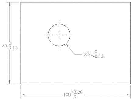
Bilateral tolerance
Bilateral tolerances for CNC machining are symmetrical around the base dimension. This means that the upper and lower limits deviate from the base dimension by the same value. As opposed to unilateral tolerances, the deviation in bilateral tolerances occurs in both the positive and negative directions.
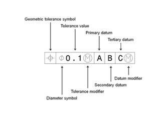
Geometric Dimensioning and Tolerancing (GD&T)
GD&T is a superior, more difficult system than standard dimensioning and tolerancing (SD&T) It not only provides the dimension and tolerance of a part but also specifies the exact geometric characteristic of the part the tolerance applies to. While SD&T covers shape, GD&T goes further to also cover geometric characteristics such as flatness, true position, and concentricity.
Tolerances tips for CNC Machining
Tolerancing is the process of adding tolerances to your dimensions when designing a part. The following are important tips to note when tolerancing for CNC machining:
- Tolerances are very important to your design. However, not all the features of a part need to be toleranced. In order to save machining time and cost, only apply tolerance to crucial features such as features that mate or interfere with other parts.
- Avoid unnecessarily tight tolerances. Tight tolerances often cause increased scrap production, special measurement tools, additional fixturing, and longer cycles. These all lead to increased machining costs.
- Usually, when tolerancing you also need to keep in mind the tolerance capability of the CNC machines that will machine your part. But when you order your parts from Xometry, you don't have to pay attention to this because we have over 5000 CNC machines in our network, which makes it possible to find a suitable machine for your project that would keep the tolerance you need.
- Keep peculiarities of the material in mind. The difficulty of machining a part to a particular tolerance is very dependent on the material the part is made from. As a result of the material flexing during machining, soft materials make it harder to hold a specific tolerance.
Read more about general tolerance standards used for subtractive manufacturing.