Hello everyone, I am Niko Mroncz, Head of Sales Engineering at Xometry Technology. Since 2010, I have been working in 3D printing-related fields, and multi-jet melt fusion (MJF) has always been the preferred process for manufacturing complex functional parts. However, if the design is not rigorous enough, issues such as warping, powder retention, or uneven surfaces may still occur. In this article, I will share some key design tips to help you create more reliable and high-performance parts for multi-jet fusion 3D printing.
Multi-Jet Fusion (MJF) is a powder bed melting technology developed by HP that uses thermal energy and chemical additives to manufacture high-strength, fine plastic parts. Unlike processes such as extrusion molding, MJF can produce dense, isotropic parts with high surface finish and excellent mechanical properties, making it highly suitable for functional prototyping and industrial production.
MJF offers several advantages: fast printing speed, high detail resolution, and the ability to manufacture complex geometries without the need for supporting structures. With efficient nesting arrangements and short cooling times, it is also one of the most cost-effective choices for medium to high-volume production. Common materials include PA 12, PA 11, polypropylene (PP), and thermoplastic polyurethane (TPU), all chosen for their durability, flexibility, and heat resistance.
Nikolaus Mroncz
Sales project manager
To obtain high-quality MJF parts, proper design is essential. Many common issues—such as warping, powder retention, or rough surfaces—can usually be avoided by following key design principles. Paying attention to factors like wall thickness, powder discharge, and part orientation can significantly improve part performance and print success rates, while keeping in mind that these issues are inherently closely related to design. Here are the most important design tips for MJF 3D printing.
1. Maintain the appropriate wall thickness
Parts with walls that are too thin may deform or become brittle, while walls that are too thick tend to accumulate heat during printing, leading to warping or uneven cooling. In MJF, these issues are especially critical due to the thermodynamic properties of powder bed melting.
Sudden changes in wall thickness can also generate internal stresses, affecting dimensional accuracy and structural performance—especially for flat or large parts.
Rule of thumb:
- For PA 12, it is recommended to design the wall thickness of at least 0.7 mm, and up to 2.0 mm for materials with higher rigidity.
- If there is an internal support structure, the wall thickness can be as thin as 0.6 mm, but to ensure consistency, 1.3 mm is recommended.
- Avoid wall thicknesses exceeding 7 mm, as excessive material can cause internal stress and deformation.
- Maintain uniform overall wall thickness to reduce warpage risk.
- Thin-walled areas can be reinforced by adding ribs or rounded corners, and stress can be distributed more evenly.
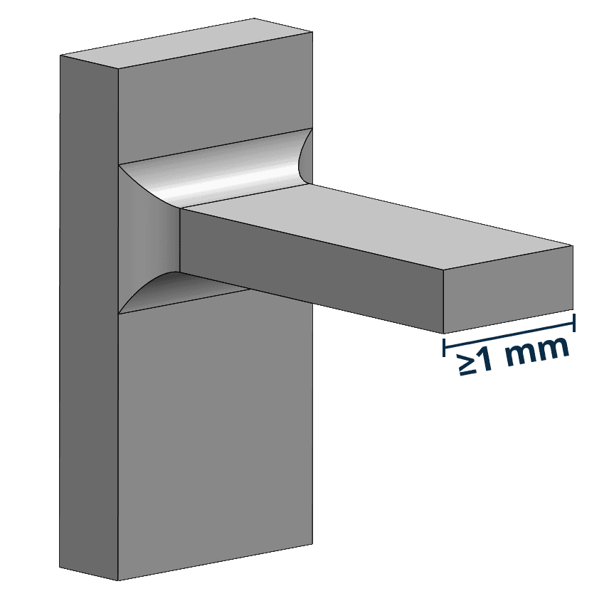
2. Reinforcing slender features
In MJF printing, slender features such as cantilevers, hooks, or snaps are especially fragile. Without proper reinforcement, they may bend, break, or warp due to lack of support or stress concentration.
This risk increases when features have a high aspect ratio or sharp transitions, especially in the Z direction, where MJF parts are more susceptible to uneven heating and cooling.
Rule of thumb:
- For cantilever arms less than 1 mm wide, the aspect ratio (length/width, L/W) should be less than 1.
- The base thickness of the cantilever remains at least 1 mm to ensure durability.
- Add fillets or reinforcing ribs at stress concentration points or extension features.
- Avoid sharp edges and use smooth, progressive transitions to reduce mechanical stress.
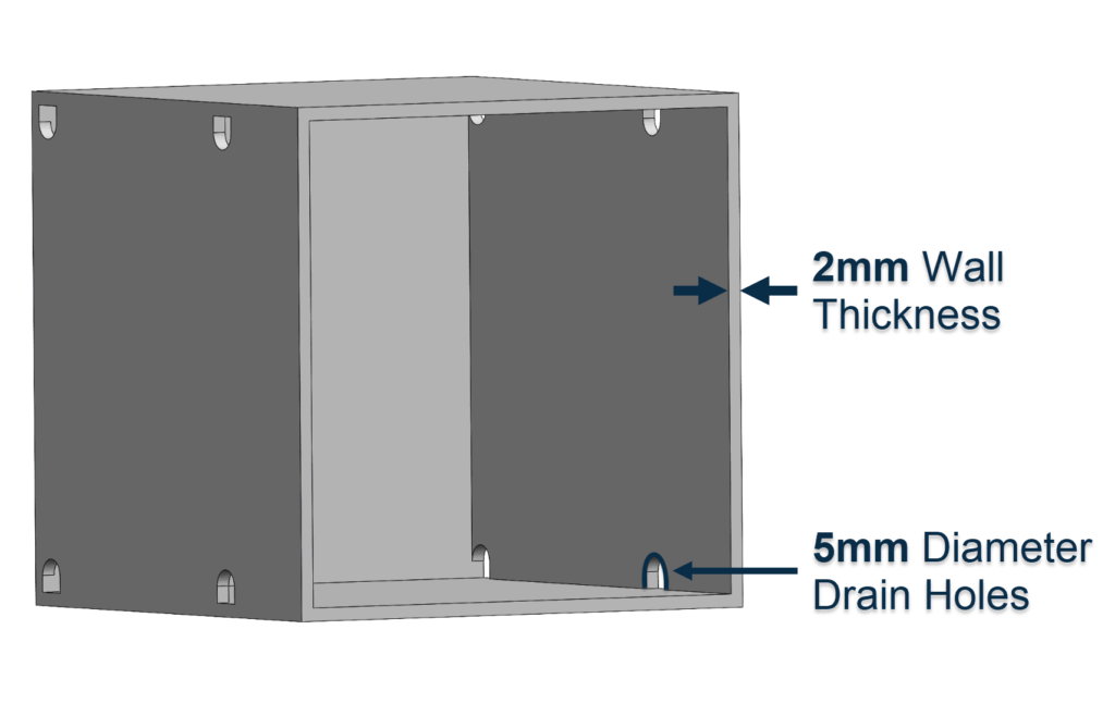
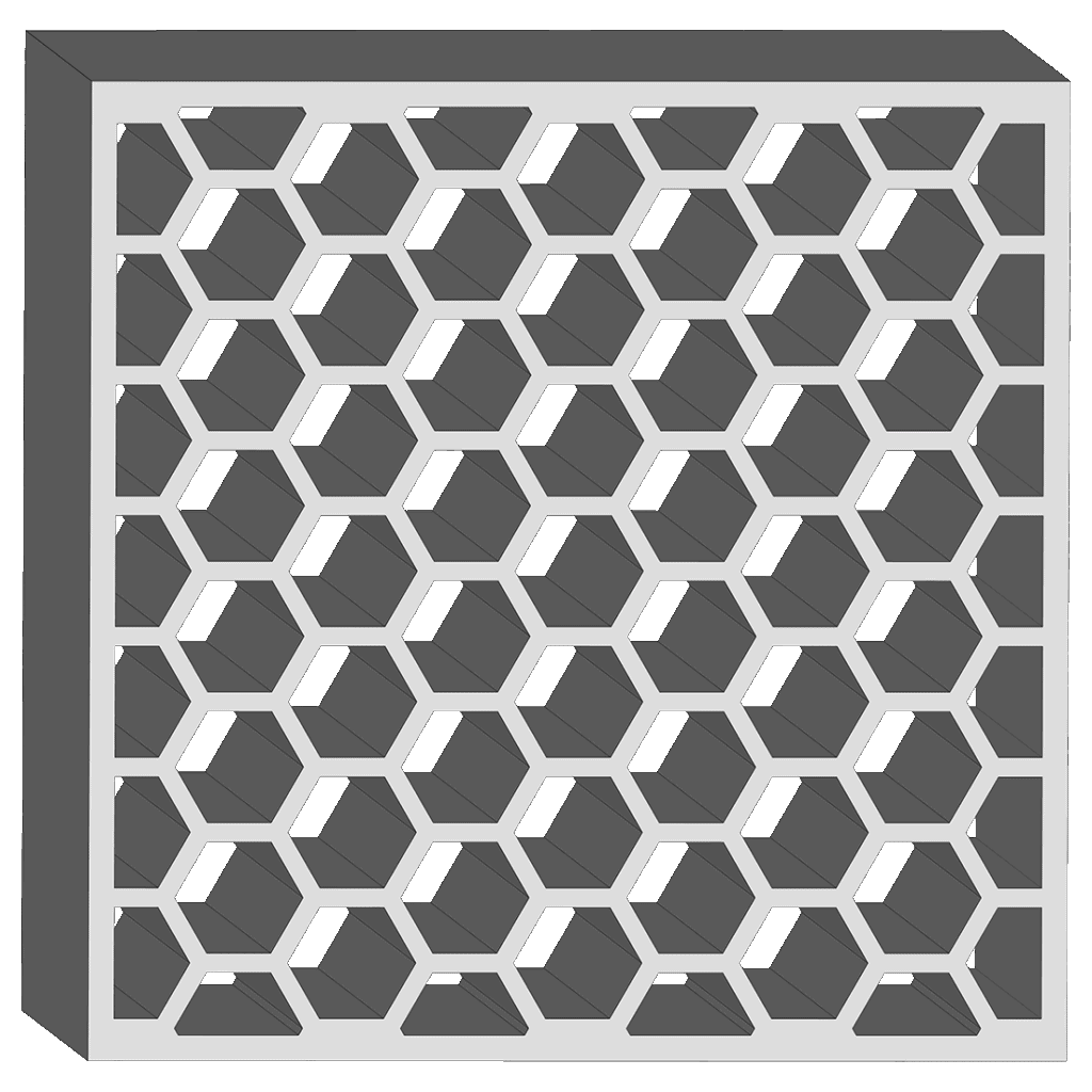
3. Optimize the hollow and internal structure
Enclosed spaces such as hollow bodies, pipes, or grilles tend to retain unmelted powder. Without proper powder separation design, retained powder increases part weight and complicates post-processing, especially in complex geometries. If left untreated, it may lead to a decline in surface quality or pipe blockages, making parts unusable or difficult to clean.
Rule of thumb:
- Set two or more powder discharge holes (each hole ≥ 5 mm) on opposite sides of the hollow part.
- The beam spacing of the grid structure should be maintained at least 1 mm to ensure effective powder discharge.
- Strip or chain features are added to the pipeline to assist in cleaning powder after printing.
- For pipes less than 5 mm wide, flexible cleaning tools can be used after printing.
- The wall thickness of hollow parts should be maintained at 2–3 mm; for fully enclosed structures, perforations should be provided.
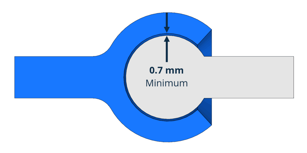
4. Leave appropriate gaps for parts
Parts designed for fitting, sliding, or rotating must leave sufficient clearance. If the spacing is too small, parts may fuse during printing or misalign after assembly. Since MJF cannot account for mechanical tolerances or friction in digital models, designers need to leave functional gaps in the design based on actual usage.
Rule of thumb:
- Simultaneous printed parts: minimum gap is 0.7 mm.
- Parts assembled later: use 0.4 mm gap, tight fit can use 0.2 mm.
- For parts with a wall thickness less than 3 mm, the gap can be as low as 0.3 mm, but testing and verification are required.
- Align parts in CAD to reflect the actual assembly position.
- Mark movable parts in drawings or instructions for attention during post-processing.
5. Avoid large flat surfaces
Large planes—especially those parallel to the printing platform—are prone to warping due to uneven heat distribution and shrinkage. Adding support ribs may exacerbate the problem, as stress is concentrated at the support position. Warped surfaces reduce dimensional accuracy, cause appearance defects, and may affect the functional fit of parts.
Rule of thumb:
- Try to avoid large flat surfaces (such as A4-sized planes).
- Wide areas are replaced with grilles, cutouts, or ribs to reduce thermal stress.
- Try to keep the flat area close to the bottom of the print to reduce the influence of the Z direction.
- The minimum thickness for wide areas is maintained at 0.3 mm to prevent warping.
6. Reduces warping of slender parts
Slender parts are especially prone to deformation due to shrinkage. When one part of a part cools faster than another, internal stress is generated, leading to warping—especially where the cross-sectional thickness suddenly changes. This deformation usually manifests as bent, uneven edges, or part dimensions exceeding tolerances.
Rule of thumb:
- Avoid designing parts with an aspect ratio greater than 10:1 (length/width) in unsupported areas.
- Increase wall thickness to balance cooling for slender features.
- Use smooth transitions to avoid stress caused by geometric changes.
- Through hollow designs or internal grilles, more uniform material distribution and cooling can be achieved.
7. Design the snap-fit structure based on MJF
Snap-and-lock is a convenient way to assemble plastic parts, but it requires precise design dimensions to ensure sufficient flexibility and prevent breakage. If the cantilever is too sharp or the beam is too rigid, it may break during assembly.
Designing MJF requires understanding the material's elastic properties and how stress should be released during the meshing process.
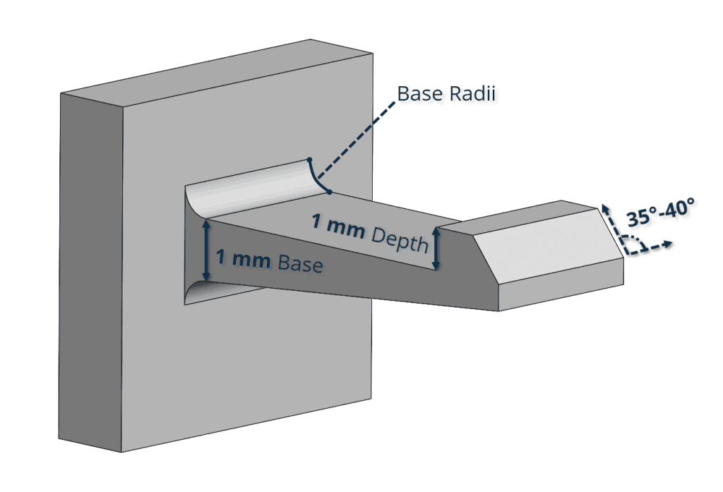
Rule of thumb:
- Cantilever base thickness: ≥ 1 mm.
- Cantilever overhang depth: ≥ 1 mm to ensure secure locking.
- Add fillets at the base of the cantilever with a radius of half the base thickness to distribute stress.
- Chamfer the tip of the cantilever to reduce the insertion force.
- The assembly angle is maintained at 35°–40°, and the cantilever beam is tapered to reduce stress.
Nikolaus Mroncz
Sales project manager
For snap-fit design, the PA 11 is the best choice. Compared to PA 12, PA 11 has a higher elongation at break, is more flexible, and is less likely to crack under repeated stress—making it ideal for hook structures that require reliable bending and reshaping requirements.
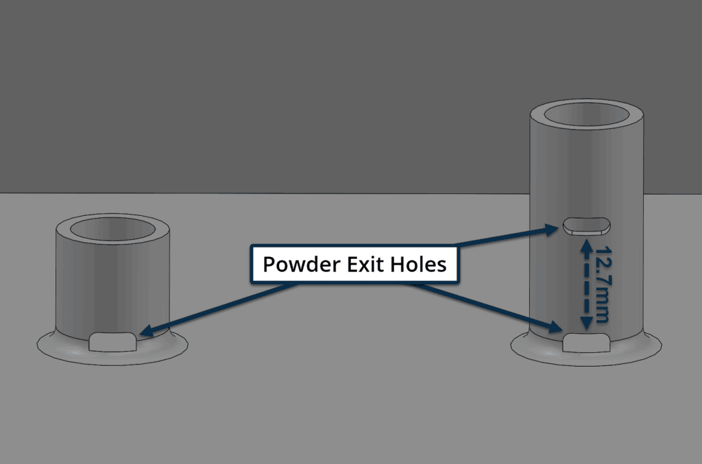
8. Avoid deep holes without powder discharge channels
Blind holes, studs, or deep cavities without powder dispensing design can easily retain powder. The deeper the hole, the harder it is to clean and usually requires manual intervention. Powder remaining in threaded holes or sockets may clog fasteners or weaken structural strength.
Rule of thumb:
- Add powder discharge holes or channels, and ensure clear line of sight.
- For deep holes (> 12.7 mm), multiple powder discharge points are set along the depth.
- Fillets are used at the bottom of the studs to reinforce features and reduce stress.
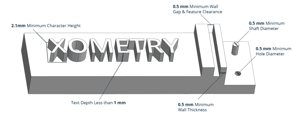
9. Use clearly legible reliefs and engraved details
Text, logos, and surface features are commonly used for brand identification or part identification, but if the size is too small, it may blur during printing and disappear during post-processing. Relief features are especially susceptible to surface treatments such as sandblasting or steam polishing, which can smooth the edges and reduce clarity.
Rule of thumb:
- The minimum line width for relief and engraving features is 0.5 mm.
- Embossing height: ≥ 1 mm; Engraving depth: ≥ 0.5 mm.
- The overall character height should be at least 2.5 mm to ensure legibility.
- For best results, the embossed text faces down, and the carved text faces up.
- Avoid embossing or engraving features smaller than 0.5 mm, as they may not withstand post-processing.
MJF 3D Printing Specification Reference Guide
The table below shows the relevant specifications for parts designed using MJF 3D printing technology.
| Specifications | More details |
|---|---|
| Maximum print volume | 380 × 284 × 380 mm, recommended size: 356 × 280 × 356 mm |
| Minimum feature thickness | 0.50 mm |
| Minimum wall thickness is recommended | Support wall 0.70 mm; No support wall: 0.70 mm |
| Thick layers | 0.08 mm |
| General tolerance | ±0.3%(±0.3 mm) |
Get high-quality MJF 3D printed parts at Xometry Technology
Effectively designing MJF 3D printing means understanding the specific limitations and advantages of the technology. By adopting the right design methods—such as maintaining uniform wall thickness, setting up powder discharge channels for closed structures, ensuring proper part clearances, and optimizing part orientation—the risk of common defects like warping, powder retention, or uneven surfaces can be reduced.
At Xomeri Technology, our engineering team will assist you in applying these design principles to achieve reliable and highly functional parts that meet your specific application requirements. Explore our MJF 3D printing services to learn how they support your prototyping or production needs.