Our Manufacturing Standards
Updated December 9, 2021

Our Manufacturing Standards
Unless we have agreed to other tolerances in your Quote, we will work to achieve and hold the tolerances noted below, which will vary per the primary manufacturing method you select. Xometry has developed a comprehensive set of Design Guides to assist you in optimizing your design for the manufacturing method ultimately selected, please consult them for key tips and tricks. In the event of a conflict between the Design Guides and this set of Xometry Manufacturing Standards, these will control.
Workmanship Standards
Orders with Xometry will meet the minimum workmanship standards outlined below (as applicable to the process). If your project requires a level of workmanship that goes beyond the standards listed below, please clearly list the requirement in your engineering drawings, purchase orders, and/or specifications.
Finished Surfaces Cosmetics
- Paint coverage on surfaces will be uniform, including adjacent materials of assemblies
- Finished surfaces will be free of defects including chips, scrapes, or other damage
Mill Steps, Tooling, and Chatter
- Tool marks on as-milled surfaces will be free of defects including burrs, chatter, tool gauges and will meet surface roughness specifications.
- Clearly indicated critical surfaces will be free of mill steps and marks across the entire surface.
- Milled surfaces will meet surface roughness specifications.
Chips, Burrs, and Sharp Edges
- All exposed edges will be free of burrs, sharp edges, and metal slivers.**
- **Sheet cut parts will not be deburred unless specified through a selected finish.
Foreign Object Debris (FOD)
- Surfaces will be free of cutting fluid, metal chips, foreign objects, and other debris.
Threads
- Threads will be fully formed and cut to specified size and class according to provided drawings.
- Threads will be free of defects, notable damage, and contamination.
Plated Surfaces
- Plated surfaces will be uniform, including adjacent surfaces of assemblies.
- Plated surfaces will be free of machining marks, scratches, pits, protrusions, or any visible bare metal.
- Some minor defects may be permissible in certain situations if they do not compromise the protective finish.
Weld Joints
- Weld joints will be finished as specified in the weld callouts of the provided part drawing.
- Welds without specific requirements will be cleaned to remove slag or other surface contamination.
- If required, weld joints will not be painted until the welding has been completed and the weld has passed inspection.
Countersinks
- Countersinks shall be round and made to print specifications and allow the proper designed fit with the mating screw.
- Countersinks will be free of burrs, chatter, or other tooling defects.
Painted Surfaces
- Painted surfaces shall be consistent and continuous in the finish.
- Painted surfaces shall be free of visible machining marks, scratches, abrasions, dust particles, fisheyes, orange peel, or bare metal.
- Painted surfaces should be reviewed against this standard at a distance of 18″ at 1X magnification.
CNC Machining and Turning
- For features of size (Length, width, height, diameter) and location (position, concentricity, symmetry) +/- 0.005” (metals) or +/- 0.010 (plastics and composites) in accordance with ISO 2768 unless otherwise specified.
- As machined surface finish is 125 Ra or better. Machine tool marks may leave a swirl-like pattern.
- Sharp edges will be broken and deburred by default. Critical edges that must be left sharp should be noted and specified on a print.
- Clear or transparent plastics will be matte or have translucent swirl marks on any machined face. Bead blasting will leave a frosted finish on clear plastics.
- For features of orientation (parallelism and perpendicularity) and form (cylindrical, flatness, circularity, and straightness) per the table below unless we have agreed to other tolerances in your Quote.
CNC Orientation and Form General Tolerances
Table: Parallelism, Perpendicularity, Cylindricity, Circularity, Flatness, and Straightness over Part Length
| Part Length | Orientation and Form Tolerance | Angularity Tolerance |
| 0 to 12″ | +/- 0.005″ | Angularity +/- ½ degree |
| 12″ to 24″ | +/- 0.010″ | Angularity +/- ½ degree |
| 24″ – 36″ | +/- 1/64″ (0.016″) | Angularity +/- 1 degree |
| 36″ – 60″ | +/- 1/32″ (0.031″) | Angularity +/- 1 degree |
| Over 60″ | +/- 1/16″ (0.063″) | Angularity +/- 1 degree |
Learn More About CNC Machining
Start Your New Instant QuoteAll uploads are secure and confidential.
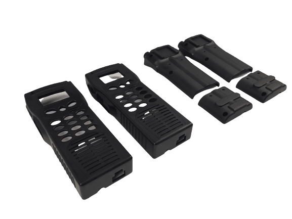
Plastic Injection Molding
- Typical mold machined tolerances are +/- 0.005″ when machining the mold and an additional +/- 0.002″ per in. when calculating for shrink rate.
- Tighter tolerances can be requested and may increase the cost of tooling. Additionally, many tight tolerances require the mold to be manufactured, sampled, and then groomed. Xometry will mill to a steel-safe condition on critical features.
Part-to-part repeatability is typically under +/- 0.004″. - Lead time stated is for first article shipment. Remaining production time is confirmed after first article approval.
- Typical first article shipments are 10 pieces but may vary based on size, origin, and material.
- Xometry cannot guarantee a perfect color match per Pantone color.
- All quotes are based upon the assumption that designs have an adequate draft, radii, and coring for manufacturability.
- Cores, side actions, and tooling strategy are determined by Xometry unless explicitly discussed.
- Gating, ejection, knit lines and parting lines are at the discretion of Xometry unless explicitly discussed.
Learn More About Injection Molding
Start Your New Instant QuoteAll uploads are secure and confidential.
Sheet Cutting Service
- Thickness tolerances are independent of cutting tolerances, as they rely on the raw stock material’s tolerance range.
- Edge to edge tolerances is +/- 0.005” nominal on the top face of the plate/sheet.
- Thicker materials may have a tolerance deviation on the bottom face due to tapers inherent in laser cutting, waterjet cutting, or plasma cutting.
- Xometry cannot guarantee flatness call outs for sheet cut materials.
- Holes of 0.100” or smaller in diameter may be slightly larger than standard tolerances due to material pierce happening near the hole’s profile.
- A small bump of material or a different edge condition may be present at the lead-in and lead-out in a cutting profile.
- Tabs may be present on parts under two inches to hold the workpiece during manufacturing using waterjet or fiber laser machines.
- Pre-finished or textured sheets, such as brushed or polished stock may have only one side with the cosmetic finish.
- Protective film may be shipped on cut products to prevent damage of cosmetic finishes.
- The edge condition of sheet cut materials will have vertical striations versus smooth edges. This affects the transparency of edges on clear plastics.
- Large burrs and tabs will be removed, but parts are not manually fully deburred before shipment unless explicitly requested or an advanced finish, such as chem films or coatings, is requested.
- Some cut materials may show a small halo discoloration from backsplash or overspray near the cut edges.
Learn More about Sheet Cutting (Laser and Waterjet)
Start Your New Instant QuoteAll uploads are secure and confidential.
Sheet Metal Fabrication
- Forming and bending: +/- 0.020″
- Bend to hole or feature: +/- 0.010″
- Linear dimensions excluding locations to bends: +/- 0.005″
- Angularity: +/- 2 degrees
- Surface roughness (blank material): Ra 125 uin max
- Surface roughness (timesave): Ra 100 uin max
- Sharp edges will be broken and deburred by default. Critical edges that must be left sharp should be noted and specified on a print.
- Certain sheet metal designs require custom tooling and will be flagged for a manual quote: hems, curled flanges and rolled sheets, stamped parts, and welded assemblies. If your part includes these features, please allow our manual quote team to review and provide you with an accurate cost and lead time.
Sheet Metal Tolerances Continued
| Flat Parts | Simple Bend / One Surface | Multiple Surface Bends |
| Sheet metal parts that utilize stock material gauge thicknesses and require no bending or milled features. All flat sheet metal parts can meet a +/-0.005” tolerance. | When designing parts with some type of bend with a standard bend radius, sheet metal tolerances are required to open. For simple bent parts, Xometry can offer a +/- 0.010” tolerance for dimensions across a single bend. The bend radius itself is constrained to a +/- 1.0°. | For dimensions measured over multiple bends, Xometry can offer a +/- 0.030. |
 |
 |
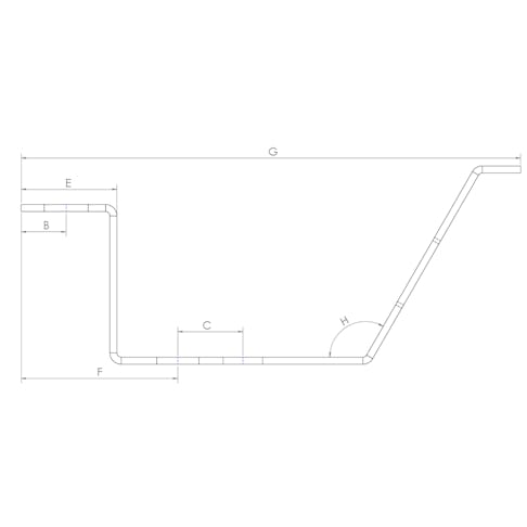 |
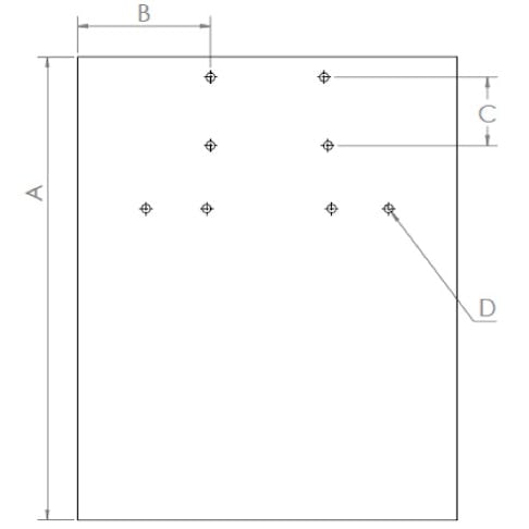
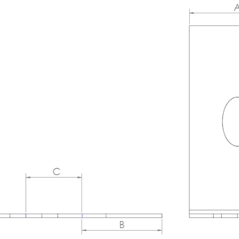
Sheet Metal Tolerances Reference Table
| Dimension Detail | Tolerance | Image Reference |
| Edge to Edge, Single Surface | +/- 0.005″ | A |
| Edge to Hole, Single Surface | +/- 0.005″ | B |
| Hole to Hole, Single Surface | +/- 0.005″ | C |
| Hole Diameter, Single Surface | +/- 0.005″ | D |
| Bend to Edge / Hole, Single Surface | +/- 0.010″ | E |
| Edge to Feature, Multiple Surface | +/- 0.030” | F |
| Over Formed Part, Multiple Surface | +/- 0.030” | G |
| Bend Angle | +/- 1 deg | H |
Urethane Casting
- Tolearance are +/- 0.010” or +/- 0.003” per inch, whichever is larger, is typical. Irregular or overly-thick geometries may cause deviances or deflection due to shrinkage.
- A shrinkage rate of +0.15% can be expected due to thermal expansion of the liquid, and the response of the flexible mold.
- Surface finish is externally smoothed to a satin or matte surface. Grow lines may be present on internal or difficult-to-access features. Polishing or custom finishes must be clearly defined and agreed upon at the point of order.
- Sharp corners and text may appear slightly rounded.

Learn More About Urethane Casting
Start Your New Instant QuoteAll uploads are secure and confidential.
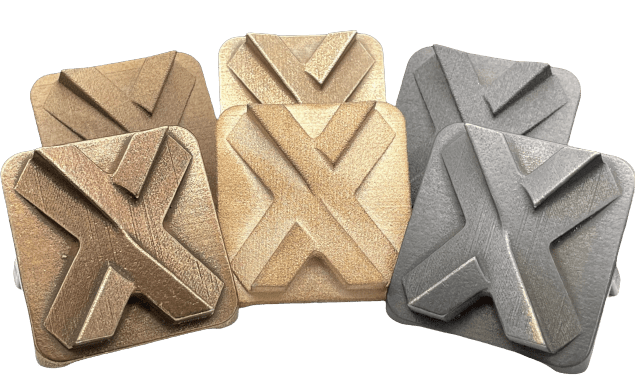
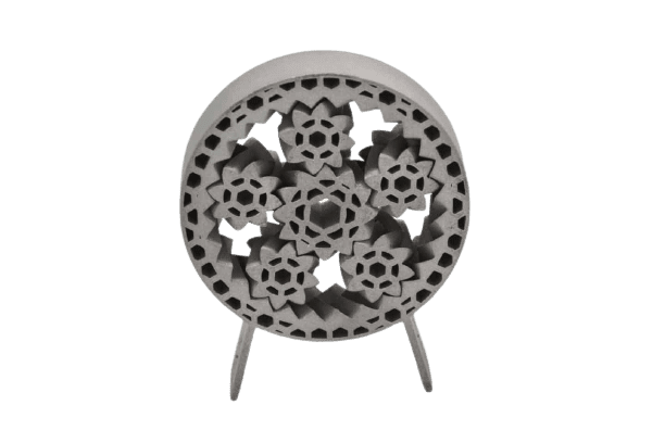
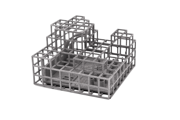
Metal Binder Jetting 3D Printing
- Metal binder jet parts are made in ExOne 420i metal, which is roughly 60% 420 stainless steel and 40% bronze infiltration.
- Depending on the part’s size and geometry, parts may shrink 0.8% – 2.5% after processing.
- Internal geometries, such as slots and holes, may shrink as much as 5%.
- Xometry does not guarantee tolerances on the first attempt at a new design.
- Improved tolerances may be possible with a manual quote review, after successful completion of a prototype build, and must be approved on a case-by-case basis.
- Metal binder jet machines print in layers of 0.004” (0.1 mm) and parts are typically oriented in the lowest Z direction.
- Parts with features below 0.03” (0.75 mm) will need to be thickened for successful processing. It is recommended the minimum feature size be above 0.04″ (1 mm).
- Modeled threads or precision features may have limited functionality as printed.
Tumble polished parts may have trapped walnut media between thin gaps or text features.

Learn More about Metal Binder Jetting
Start Your New Instant QuoteAll uploads are secure and confidential.
Carbon DLS™ 3D Printing
- +/- 0.005” for the first inch is typical, plus +/- 0.002” for every inch thereafter. However, Xometry does not guarantee tolerances on the first attempt of a new design. Tolerance expectations can vary across different materials (e.g. elastomeric versus rigid materials).
- Stresses during build, support strategy, and other geometry considerations may cause deviation in tolerances and flatness.
- Parts with thicker geometries, flat or broad parts, and parts with uneven wall thicknesses may be prone to significant deviations or warp.
- Modeled threads or precision features may have limited functionality as printed. Tapping or the addition of threaded inserts is recommended for best function.
- Improved tolerances may be possible with a manual quote review, after successful completion of a prototype build, and must be approved on a case-by-case basis.
DMLS 3D Printing
- +/- 0.005” for the first inch is typical, plus +/- 0.002” for every inch thereafter. However, Xometry does not guarantee tolerances on the first attempt of a new design. Tolerance expectations can vary across different materials (e.g. stainless steel versus aluminum).
- Internal stresses during build, support strategy, and other geometry considerations may cause deviation in tolerances and flatness.
- Items and geometries which require strict flatness are not a good fit for this process.
- Modeled threads or precision features may have limited functionality as printed. Tapping or the addition of threaded inserts is recommended for best function.
- Expected surface roughness is 150-400 µin RA, depending on build orientation and material used for the build.
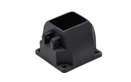
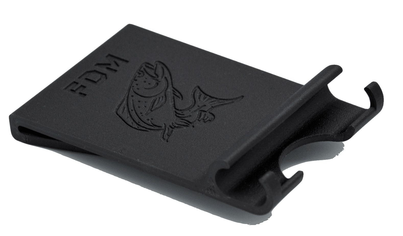
FDM 3D Printing
- +/- a single build layer thickness for the first inch and +/- .002” for every inch thereafter.
- 0.010” layer thickness is used for parts fitting within a 14” X 16” footprint (Fortus 450)
- 0.013” layer thickness is used for parts exceeding 14” X 16” footprint (Fortus 900)
- 0.008″ layer thickness used for Prototyping PLA (9.8″ x 8.2″ x 8.2″, Prusa MK3S desktop FFF)
- Guaranteed tolerances may be possible with a manual quote review, and must be approved on a case-by-case basis.
- Xometry chooses optimal build orientation taking into consideration overall surface quality and minimum build time unless otherwise specified.
- Minimum resolvable feature size, including positive text features, is at least 0.035” (0.045” or greater is safest).
- Modeled threads or precision features may have limited functionality as printed. Tapping or the addition of threaded inserts is recommended for best function.
- Horizontal holes and protrusions will build slightly oblong due to stair stepping from layers.
- Nylon 12, ULTEM 9085, and ULTEM 1010 parts with thicker geometries, flat or broad parts, and parts with uneven wall thicknesses will be prone to significant deviations or warp due to variable thermal shrinkage and stress.
HP MJF 3D Printing
- +/- 0.012” up to 4″ is typical, plus +/- 0.003” for every inch thereafter.
- Parts with thicker geometries, flat or broad parts (>7”), and parts with uneven wall thicknesses will be prone to significant deviations or warp due to variable thermal shrinkage and stress.
- Modeled threads or precision features may have limited functionality as printed. Tapping or the addition of threaded inserts is recommended for best function.
- Natural grey color may be inconsistent depending on feature size and build orientation. Dyed black is recommended for production parts.
Guaranteed tolerances may be possible with a manual quote review, and must be approved on a case-by-case basis.
Polyjet 3D Printing
- +/- 0.004” for the first inch is typical, plus +/- 0.002” for every inch thereafter.
- Minimum feature size of 0.050” can be built with consistency.
- Rubber-like materials represent an approximation of shore A values and may vary between geometries.

SLA 3D Printing
- Guaranteed tolerances may be possible with a manual quote review, and must be approved on a case-by-case basis.
- Modeled threads or precision features may have limited functionality as printed. Tapping or the addition of threaded inserts is recommended for best function.
- Tolerances for Standard and High Resolution options are described in the table below
Tolerances for SLA, Standard and High Resolution
| Feature | Standard Resolution | High Resolution |
| Tolerance, XY Plane | +/- 0.005” for the first inch is typical, plus +/- 0.002” for every inch thereafter. | +/- 0.005” for the first inch is typical, plus +/- 0.002” for every inch thereafter. |
| Tolerance, Z Plane | +/- 0.010” for the first inch is typical, plus +/- 0.002” for every inch thereafter. | +/- 0.010” for the first inch is typical, plus +/- 0.002” for every inch thereafter. |
| Minimum linear feature size | Under 0.030” are at risk and under 0.020” will not build. | Under 0.020” are at risk and under 0.010” will not build. |
| Minimum radial feature size | 0.035″ | 0.030″ |
| Layer height | 0.004″ | 0.002″ |
SLS 3D Printing
- XY Planes: +/- 0.005” for the first inch is typical, plus +/- 0.002” for every inch thereafter.
- Z Direction: +/- 0.010” for the first inch is typical, plus +/- 0.002” for every inch thereafter.
- Parts with thicker geometries, flat or broad parts (>7”), and parts with uneven wall thicknesses will be prone to significant deviations or warp due to variable thermal shrinkage and stress.
- Modeled threads or precision features may have limited functionality as printed. Tapping or the addition of threaded inserts is recommended for best function.
- Guaranteed tolerances may be possible with a manual quote review, and must be approved on a case-by-case basis.

General Manufacturing: Mating and Flexible Features
- Xometry is not responsible for the fit of mating parts.
- Xometry is not responsible for the function of snap tabs, clips, or living hinges.

Change Log
Added change log. Improved page formatting. Updated injection molding tolerances to reflect initial tooling tolerances.
Added plastic tolerances to CNC machining.
Updated notes for 3D printed threads, clarified tolerances on FDM, HP MJF, and SLS.
Related FDM tolerances to layer height based on platform used. Adjusted HP MJF and SLS notes on parts with uneven wall thicknesses or large geometries.
Added metal binder jetting manufacturing standards.
Incorporated language around PLA under FDM 3D Printing.
Added layer height to SLA guidelines. Incorporated workmanship standards.
Introduced sheet cutting manufacturing standards.