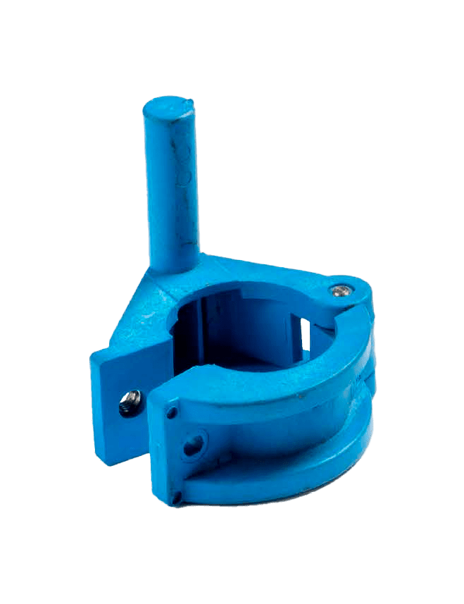
Proper dimensions and tight tolerances in injection moulding are the most important things with respect to design and manufacturing. The part could underperform or even fail if they are not adhered to correctly within a design. Especially for plastic injection-moulded complex parts, tight tolerancing is an important feature. In general, a typical tolerance for injection moulding is +/-0.1mm while a very tight tolerance is +/- 0.025mm.
Factors influencing the tolerances of part & how to reduce their impact
Shrinkage
Different materials have different rates of shrink — the higher the shrink rate, the less possibility to achieve a tight tolerance. Crystalline materials (e.g PEEK, PA, PP) generally hold poorer tolerances than amorphous materials (e.g PE, PC, PS). This is because crystalline materials go through a phase change from a crystalline solid (densely packed molecular structure) to an amorphous melted fluid (less dense molecular structure), thus resulting in a volume change.
On the other hand, amorphous materials stay amorphous even when melted and don’t experience a drastic volume change. Hence, they shrink less.
| Amorphous resins | Semicrystalline resins | Cost |
| High-Performance/Speciality Polyetherimide or PEI Strength: High Heat & Chemical Resistance: High Applications: Aerospace | High-Performance/Speciality Polyetheretherketone or PEEK Strength: High Heat & Chemical Resistance: High Applications: Bearings, medical implants | Expensive |
| Engineering Polycarbonate or PC Transparent Strength: Moderate Heat Resistance: High Electric Insulator: High Applications: Electrical, windows | Engineering Polymide or PA (Nylon) Strength: Moderate to high Chemical Resistance: High Abrasion Resistance: High Shrinkage and Warp: Low Applications: Auto parts, textiles | Moderate |
| Commodity Polystyrene or PS Transparent Strength: Low Heat Resistance: Low Applications: Cutlery, cups | Commodity Polypropylene or PP Flexibility & Toughness: High Chemical Resistance: High Fatigue Resistance: High Applications: Bottles, crates & cases, living hinges | Inexpensive |
Injection moulds are precision machined from aluminium or steel with CNC machining to typical tolerances of about +/-0.1 to 0.7mm. When plastic is injected into a mould, it cools and shrinks. The rate of shrinkage is a function of the resin or plastic being used. Each mould is machined slightly larger than the part to accommodate for shrinkage of the resin on cooling.

How to reduce shrinkage
Since different materials have different shrinkage rates, it’s better to check out the rate for the desired plastic to assess the shrinkage beforehand. More info on shrinkage of various plastics here.
Although this shrinkage rate is very predictable, slight variations in the resin affect the shrinkage and hence the final part tolerance. The shrinkage variation gets larger as the part gets larger, so depending on the material you should expect the tolerance due to shrinkage to be roughly +/- 0.05 mm/mm. The result is that, for example, a 100 mm ABS part will have a tolerance of roughly +/- 0.28 mm. Part to part, the repeatability is very consistent, with little or no deviation.
Warpage
All parts shrink as the resin cools in the mould. Parts with uniform wall thickness shrink uniformly and avoid warp and sink marks. Non-uniform walls will cool and shrink at different rates, increasing the amount of warp inherent in the part design.
How to reduce warpage
If it is necessary to have a non-uniform wall thickness, the change in thickness should not exceed 15% of the nominal wall thickness and always use a smooth or tapered transition to ensure a successfully moulded part. The table below shows recommended wall thicknesses to avoid warpage.
| Material | Recommended Wall Thickness |
| ABS | 1.1-3.5 mm |
| Acetal | 0.7-3.0 mm |
| Acrylic | 0.6-12 mm |
| Liquid crystal polymer | 0.7-2.9 mm |
| Long-fiber reinforced plastics | 1.9-27 mm |
| Nylon | 0.7-2.9 mm |
| Polycarbonate | 1-3.8 mm |
| Polyester | 0.6-3.1 mm |
| Polyethylene | 0.7-5 mm |
| Polyphenylene Sulphide | 0.5-4.5 mm |
| Polypropylene | 0.88-3.8 mm |
| Polystyrene | 0.88-3.8 mm |
| Polyurethane | 2-19 mm |
Check our design tips for injection moulding.
Thermal expansion
Temperature is another consideration during the design phase. Holding tight tolerances can be a challenge with most resins and plastics because of their high thermal expansion rates. Even though plastic parts can hold tight tolerances in a controlled environment, it doesn’t mean that they maintain these dimensions with time and as the temperature changes, for example, when using end parts in real-life conditions outdoors. This is critical when plastic parts are combined with other material types such as metals and when the part is used in an environment with extreme temperature changes.
How to reduce the effect of thermal changes
Since the environment and the external temperature conditions influence the behaviour of plastic, engineers should know in advance which injection moulding material has to be ideally used. If a wrong material is selected which responds unpredictably to environmental conditions, tight tolerances cannot be held.
Consider that plastics typically have large thermal expansion coefficients. The tolerances are different in a controlled environment and whereas they are put to work in real conditions, they fail. For example, ULTEM and PEEK plastics are more thermal resistant than ABS or PC.
Part design
It is the major factor in determining the tolerances of the part. Making improvements during the design phase of a project not only helps ensure tight tolerances during production but also helps improve quality, manufacturability, reduce costs and end-user satisfaction.
Part geometry, overall size, and wall thickness requirements can all have an influence on tolerance control. Thick walls may have different shrink rates within the thick sections, making it tougher to hold tight tolerances since the part shrinks differently at different sections. The size of the part has an impact if the dimension with the tight tolerance is large (it’s easier to hold tight tolerances in smaller areas). The larger the dimensions, the larger the overall shrinkage and makes it more challenging to control and hold a tight tolerance.
Solution
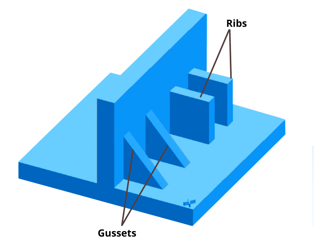
Identifying tight tolerances very early in the design phase allows engineers to determine the factors that influence injection moulding tolerances such as part geometry, part size and features like wall thickness. Maintaining uniform wall thicknesses throughout a part is an important factor to avoid uneven shrink rates which lead to deformities and hamper the part’s efficiency and its ability to hold tight tolerances. In most cases, design features like support ribs or gussets are more effective in providing strength rather than increasing wall thickness.

Part complexity
Part complexity also impacts material flow and tooling design because filling the parts quickly into the mould, maintaining proper tooling temperature, and cooling process management is important for tight tolerancing.
Solution
Even though this part would be more relevant for the manufacturers, it’s still important to keep this aspect in mind at the design stage. It is advised to make the design as simple as possible so as to avoid undercuts. If complexity is inevitable, it’s better to design a better mould with side actions. Properly designed mould tools play an important role in ensuring that parts cool properly and adhere to strict tolerance standards.
By checking injection pressure, resin viscosity, and mould fill time, engineers can track and adjust the variables to ensure the right pressure, proper heating and cooling during the process. Mould fill analysis is needed for accurate predictions regarding tolerance influencing factors like mould temperatures, its heating and cooling, shrinkage, and warpage
Tooling
There are three types of tools in Injection moulding:
- Single cavity tool – Produces single part for a single shot of plastic
- Multi cavity tool – Produces multiple parts for a single shot of plastic
- Family cavity tool – Produces all the parts of an assembly for a single shot of plastic

Tool design, tool material and cavitation are the main factors that affect the ability to achieve the desired tolerance. The need to heat and cool tools, the number of cavities of it, can make achieving tight tolerances more challenging. If tooling design fails to provide consistent, repeatable cooling, shrink rates rise and lead to poor tolerances. As an example, a multi-tool or family tool will have more cavities and hence more cooling support has to be given to them. Tight tolerances can be tough if the cavities of a tool are designed in a manner that can lead to errors, either due to the design itself or factors like pressure or temperature of the tool.
Solution
This part is also more relevant for the manufacturers, but it can still be useful for the designers. Manufacturing processes involve a significant number of factors that affect the viability and quality of a part, and process controls are a means of calibrating these factors so as to minimize deviation.
Temperature and pressure sensors embedded in the mould play a key role in developing process controls, as they provide real-time feedback on these parameters, allowing rapid adjustments and changes if unacceptable changes are detected. Once these factors are controlled accordingly, the mould tooling will be able to create parts with tight tolerances and minimal deviation. Moldfill analysis is also another method in determining the condition of the mould.
Other considerations
The most important thing before manufacturing is to determine whether tight tolerances are required for the part. Tight tolerances may not be required for your part design or depending on the required end-use. Designer engineers often set a tolerance in the CAD software and all dimensions are toleranced according to that tight tolerance number. In reality, the part might not need tight tolerances. Tighter tolerances may equate to increased production and development costs.
Conclusion
Xometry Asia offers injection moulding services online for both prototypes and large batches. With a network of more than 10,000 partners worldwide, Xometry is able to deliver injection moulding parts in up to 3 days. Upload your CAD files to Xometry Instant Quoting Engine to get an instant quote with various manufacturing options available for injection moulding.

