Injection moulding is a manufacturing process that involves the injection of molten material into a mould to produce a part. Various materials can be used for this process like thermoplastics, polymers, or elastomers. The molten material is fed into a barrel through a hopper, where it is heated, melted and mixed. It is then injected into the mould. After solidification, the material takes up the shape of the cavity of the mould. The injection moulding process is widely used in large volume production as it produces comparatively low scrap production and has high repeatability.
The versatility of the injection moulding process demands much broader design considerations. Most of the design considerations will be made on the mould after setting out the product requirements. Some of the factors that affect the design include: how the part will be used (singular product or for assembly), its dimensional and mechanical requirements, and its ability to withstand elements such as chemicals or pressure. Some vital tips to consider when designing for injection moulding are explored below.
Carefully choose materials suitable for your design
Different materials offer varying properties. For example, some injection moulding materials provide more dimensional stability than others. Similarly, some bond better with adhesives than others. Material design considers the following: temperature, pressure, biological and chemical interactions. Thermoplastic resins can be broadly classified into amorphous and semi-crystalline. While the semi-crystalline thermoplastics offer better chemical and electrical resistance, their amorphous counterparts are much more dimensionally stable and more resistant to impact. Material selection can affect the required tolerance level or certain features, like wall thickness.
At Xometry we offer various injection moulding materials including plastics, elastomers, and silicone rubbers.
Take into account the part tolerance
Moulds are generally prepared with tight tolerances, usually with CNC tolerance up to ±0.005 mm. But as plastics cool, shrinkage occurs, depending on the material. Some polymers shrink more than others. For example, while you can expect a maximum shrinkage of 0.5% in PLA, PEEK may shrink by as high as 1.5%. Always take shrinkage into account when designing a part and applying tolerances, taking the type of material used into consideration.
Choose the right wall thickness
The following are the recommended wall thicknesses for different materials:
- ABS: 1.143 mm - 3.556 mm
- Acetal: 0.762 mm - 3.048 mm
- Acrylic: 0.635 mm - 12.7 mm
- Liquid Crystal Polymer: 0.762 mm - 3.048 mm
- Long-Fiber Reinforced Plastics: 1.905 mm - 27.94 mm
- Nylon: 0.762 mm - 2.921 mm
- Polycarbonate: 1.016 mm - 3.81 mm
- Polyester: 0.635 mm - 3.175 mm
- Polyethylene: 0.762 mm - 5.08 mm
- Polyphenylene Sulfide: 0.508 mm - 4.572 mm
- Polypropylene: 0.889 mm - 3.81 mm
- Polystyrene: 0.889 mm - 3.81 mm
- Polyurethane: 2.032 mm - 19.05 mm
Also, walls should be evenly thick. Uneven wall thickness leads to sink marks. A sink mark is a local surface depression due to the thicker sections' slow cooling. Keep wall thickness uniform as much as possible. However, where it is unavoidable to have non-uniform wall thicknesses, the difference in thickness must not be more than 15% of the nominal thickness. We also recommend using a tapered or smooth transition.
Add draft angles to your design
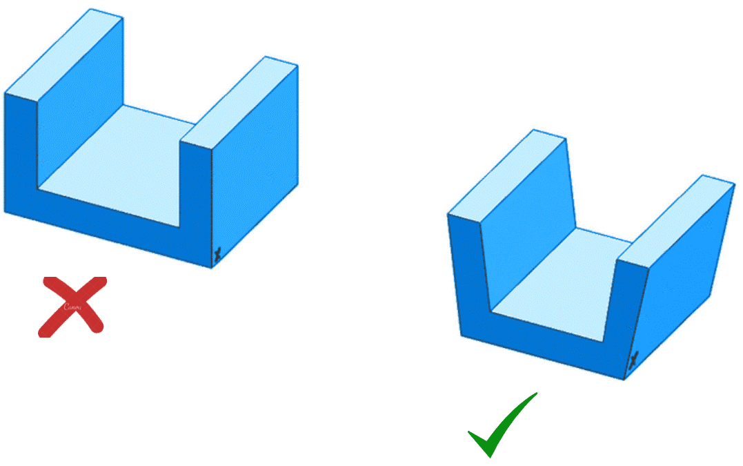
Many material removal processes such as CNC machining can produce vertical walls. However, creating a part for injection moulding with vertical walls will cause the part to get stuck, particularly at the core, as the part contracts on cooling. If too much force is applied to eject the part, the risk of damaging the ejector pins and even the mould becomes very high. Design the walls of parts with a slight slant to avoid this problem. This slanting is called draft.
Due to the high complexity it creates in designing, draft is usually added at the final stages of the part design. Different surfaces require varying drafts. Textured surfaces require the most draft. Some common surfaces found in injection moulding and their minimum draft angles are as follows.
- For “near-vertical” requirements: 0.5°
- Most common situations: 2°
- All shutoff surfaces: 3°
- Faces with light textures: 3°
- Faces with medium textures: 5°+
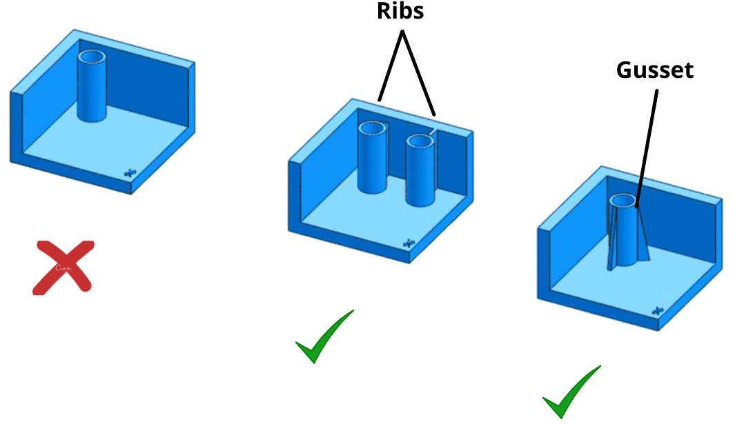
Add ribs and gussets to certain parts
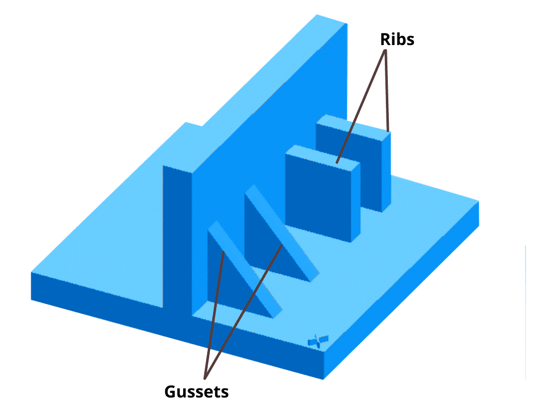
Certain parts require ribs. Ribs and gussets give additional strength to parts and help to eliminate cosmetic defects like warping, sink and voids. These features are essential for structural components. Therefore, it is preferable to add them to parts rather than increasing the thickness of parts to increase strength.
However, if not properly designed, this can lead to shrinkage. Shrinkage happens when the cooling rate of certain parts is much faster than others, resulting in the permanent bending of some sections. The warping can be effectively reduced by keeping the rib thickness between 50 – 60% of that of the wall it is attached to.
Add radii and fillet to part design
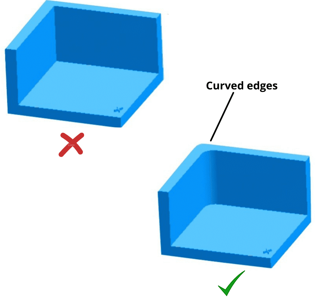
Applying radii to parts, when possible, eliminates sharp corners, which improves the flow of material and the part's structural integrity. Sharp corners cause weakness in the part as the molten material is made to flow through the corner or into the corner. The only places that sharp corners are unavoidable are the parting surfaces or shut off surfaces.
Radii and fillets also aid in part ejection as rounded corners are less likely to get stuck during ejection than sharp corners. Furthermore, sharp corners are also not structurally advisable as they lead to stress points that can fail. Radii help to smoothen out the stress on the corners.
Also, including sharp corners in your part will exponentially increase the cost of production as this would require the mould to feature sharp corners that can only be achieved using very expensive manufacturing techniques. Always add radii of a minimum of .5T for inner radii and 1.5T for outer radii, where T is the thickness of the part.
Add snap fits to your parts
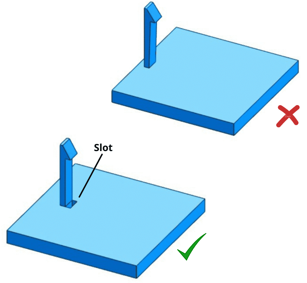
Snap fits are obtainable through undercuts. The straight-pull mould, which consists of two halves, and is the most straightforward design, is not suitable to manufacture parts with undercut features. This is due to the difficulty in machining such a mould with CNC and the tendency of the material to get stuck on ejection. Undercuts are usually created using side cores. However, side cores significantly increase tooling costs. Luckily there are some design tips to achieve the function of an undercut without using side cores. One way of doing this is by introducing a slot instead.
This is also referred to as a pass-through core. Another way is to adjust or move the parting line of the part. When doing this, also adjust the draft angle accordingly. Moving the parting lines is most suitable for undercuts that are on the outside of the part. You can also use stripping undercuts, also referred to as bump offs. However, only use this feature when the part is flexible enough to deform and expand during ejection from the mould.
Also, give enough clearance: bump-offs must have a lead angle of 30° to 45° for effective ejection.All these alternatives to expensive side cores require significant redesigning of the part. When the redesign of a part is not possible due to the possibility that it may affect the functionality of the part, then you have to employ sliding side-actions and cores to deal with undercuts. These features slide in as the mould closes and slide out as it opens. The side-cores must move perpendicularly and have appropriate draft angles.
Attach bosses to side walls or ribs
Bosses are cylindrical features, moulded into a part, that serve to receive pins, inserts, or self-tapping screws, for the purpose of assembling or mounting parts. These features should not be freestanding. Always attach bosses to a side wall or ribs to ensure the structural integrity of the part. For self-tapping applications, the outer diameter of the boss should be two and a half times the screw diameter.
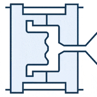
Choose the right gate placement
Gates are entry sections through which the molten material enters the mould. The wrong placement of the gate could lead to an uneven flow of the material in the different sections of the mould. This will result in the formation of streaks or patterns known as flow lines.
In addition to the strategic placement of the gate, increasing the injection can also ensure even flow throughout the mould cavities. Always make provision for the gate on the part, where it won't affect the part's functionality or aesthetics
Xometry’s injection moulding services
At Xometry Asia, we offer injection moulding services with over 30 materials, such as plastics, synthetic and silicone rubber, and elastomers. Simply head over to our Instant Quoting Engine to upload your model and select your part preferences to receive a 24h quote.