Injection molding defects—such as flash, warping, and shrinkage marks—directly affect the appearance and structural performance of the part. To prevent these problems, theory alone is not enough; a practical understanding of their root causes and effective solutions is also necessary. By using Design Manufacturability (DFM) methods, we understand the causes of these defects and preventive measures to achieve flawless production.
By applying best practices in design, mold engineering, and process control, these defects are largely predictable and avoidable. This article will identify common injection molding defects, analyze their root causes, and provide practical solutions to help you achieve stable, high-quality injection molded part production.
Quick reference defect comparison table
The table below summarizes various types of injection molding defects, highlighting their causes as well as possible design solutions or preventive methods. More details will be provided in the next section.
| Injection molding defects | Cheng Yin | Quick design tips |
|---|---|---|
| Flash: A thin plastic layer that seeps out along the parting line or ejector pin | Gate lines or ejector pins with too small radius, uneven wall thickness, parting lines in high-stress areas, excessive injection pressure, sharp corners, mold wear | • Place the parting line in an inconspicuous area • Avoid sharp corners at mold parting points • Maintain uniform wall thickness |
| Short Shots: Incomplete filling; Missing parts or some walls that are too thin | Thin walls, steep transitions, complex flow channels, and low injection pressure | • Wall thickness maintained at >0.8 mm • Avoid sharp turns • Choose low-viscosity resin |
| Gate Vestige: Residual material is visible at the gate after injection molding | Gates that are too large, poor edge trimming, or improper placement | • Use tunnel gates or latent gates • Place gates on hidden surfaces • Confirm trimming during the DFM stage |
| Improper positioning of the parting line: the parting line passes through key or visible areas | Parting lines pass through key or visible areas | Poor mold alignment and improper geometric design |
| Bubbles and Voids: Air layers inside or on the surface of parts | Poor exhaust, moisture content, and uneven cooling | • Maintain uniform wall thickness • Avoid sudden changes in thickness • Add ribs or vent channels |
| Flow lines: wavy streaks or patterns on the surface of a part | Low speed/low temperature, rapid geometric changes | • Use smooth transitions and rounded corners • Rounded sharp corners • Gates arranged in thick areas |
| Burn marks: dark or yellow marks formed at the end of the runner due to gas retention | High speed, poor exhaust, melt overheating | • Add vent holes or ejector pins • Reduce injection speed • Avoid dead-end runners |
| Sink marks: surface depressions or small pits formed by uneven cooling | Improper mold design, thick zones, insufficient holding pressure, and poor cooling | • Choose suitable materials such as ABS, PC, or PMMA • Maintain uniform wall thickness • Rib-to-wall thickness ratio ≤60 % • Core thickness zone |
| Surface Delamination: The surface layer of the injection-molded part peels off, exposing the underlying material | Materials are incompatible and contaminant | • Use of a single material • Confirm compatibility with secondary coatings |
| Weld Lines / Knit Lines: Visible joints formed at the junction of the melt flow lead | Flow interruption, low temperature, poor exhaust | • Avoid sharp obstructions • Reinforce near the weld • Optimize gate position |
| Warping: Deformation caused by uneven cooling or shrinkage | Uneven cooling or contraction | Large variations in wall thickness and improper material selection |
| Jetting: Serpentine patterns formed by high-speed melt flow | High-speed melt flow creates serpentine patterns | Small gate, low mold temperature, and high injection speed |
| Vacuum Voids: Internal hidden voids formed by stagnant air | Thick zone, gas retention, low pressure | • Core thick zone • Add cutouts |
| Discoloration: Unexpected color differences on the surface of parts | Resin degradation and pollution | • Specify color codes • Avoid complex color transitions • Use heat-resistant pigments |
| Splay Marks / Silver Streaking: Silver-white streaks on the surface caused by moisture or contamination | The resin contains moisture, has high shear, and dries poorly | • Avoid sharp gates and edges |
Injection molding defects caused by mold design
Defects originating from mold design are usually caused by improper initial mold design or insufficient mold maintenance. Such issues often require large-scale, expensive, and time-consuming repairs, including major mold modifications or even complete mold reopening. Addressing mold-related issues early in design through comprehensive Design for Manufacturability (DfM) analysis can effectively avoid costly production interruptions.
The main mold design-related defects include:
- Short Shots
- Flash
- Bubbles and Voids
- Gate Residue (Gate Vestige)
- Improper Parting Line Placement
#1 Not fully charged
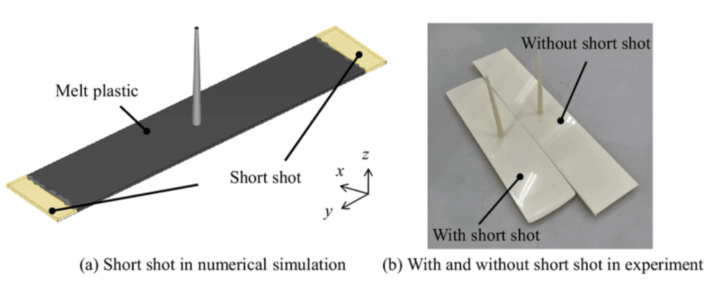
Short shots refer to mold cavities not being fully filled, resulting in missing or incomplete parts of the part. These defects typically occur in thin-walled areas or areas far from the gate, ultimately leading to part scrapping.
Root causes: thin-walled or narrow areas, abrupt transitions, excessively long flow paths, poor gate position, insufficient injection pressure, and rapid cooling.
Design Modification:
• Maintain consistent wall thickness and ≥ 0.8 mm, unless the resin used supports thinner wall thicknesses.
• Use rounded corners and smooth transitions instead of sharp corners to maintain flow.
• Avoid overly long or narrow flow paths—add guide ribs or adjust gate positions to reduce flow distance.
• Use MoldFlow or similar tools for flow simulation during the design validation phase.
• Maintain appropriate filling ratios when designing ribs and bosses; The thickness of the ribs should be about 60% of the thickness of adjacent walls.
Pro tip: For parts with thin walls or complex features, choosing low-viscosity resin helps improve fluidity in complex geometries and reduces the risk of unfilled defects.
#2 Flash
Flash forms when plastic seeps into mold gaps, usually appearing as thin, flake-like burrs along the parting line, ejector pin, or gate.
In most cases, this defect only affects appearance, but if excessive, it may require post-processing and may even lead to dimensional tolerance issues.
Root causes: excessive injection pressure, poor mold fit, mold wear, sharp transitions in sealed areas, overly complex parting geometry, and accumulated tolerances.
Design Modification:
• Keep parting lines away from sharp corners and appearance areas.
• Apply consistent demolding angles to avoid overly tight or mismatched closed areas.
• Keep wall thickness transitions smooth near the parting line to prevent local pressure buildup.
• Verification of the alignment line position early on through DFM review.
• Ensure injection pressure and clamping force do not exceed mold tolerance ranges—simulate if necessary.
#3 Improper positioning of the parting line
The parting line is the part where the two halves of the mold (the core and the cavity) join. Improper placement of parting lines can cause visible seams or flash, especially when passing through functional or visual features, which can easily lead to poor assembly, increase post-processing steps, or trigger appearance defects.
Fundamental causes 😀 incomplete FM analysis, poor mold alignment, and neglected geometric transitions.
Design Modification:
• Plan the position of the parting line in advance before finalizing appearance or functional geometry.
• Avoid placing parting lines on marks, snaps, sealing surfaces, or alignment features.
• Aligning the parting lines with sharp corners, ribs, or grooves to naturally hide them.
• Use symmetrical parting lines whenever possible to balance the top force.
• Verify the parting line position during the DFM review and confirm the mold opening direction.
Pro tip: If the design requires multiple sliders or inserts, simplify as much as possible—the complexity of parting lines can significantly increase mold costs.
#4 Bubbles and Holes
Bubbles and voids may appear as visible bubbles or hidden voids, which can reduce part strength, cause dimensional errors, or leave surface defects. Common causes are air stagnation or uneven cooling. Such defects can weaken structural integrity, affect dimensional accuracy, and compromise the final appearance.
Root causes: resin moisture content, poor venting, sudden thickness changes, uneven wall thickness design, and high material shrinkage.
Design Modification:
• Maintain consistent wall thickness—thickness variation is controlled within ±10%.
• Avoid abrupt transitions from thick to thin; Uses gradient transitions to ensure uniform flow and cooling.
• Uses ribs instead of solid thick blocks to promote even filling.
• Adding exhaust structures in deep cavities or enclosed areas.
• For thick-walled structures, choose materials with low shrinkage rates (such as ABS instead of HDPE).
• Simulates filling and cooling processes to detect and eliminate areas of gas retention.
Pro tip: Voids usually appear in areas thicker than 4 mm—hollow out thick areas to prevent shrinkage and internal defects.
#5 Gate residue
Gate residue refers to visible marks or protrusions left at the plastic injection site. Although the impact is usually minor, in assemblies with high aesthetic requirements or tight fit, aesthetics or functionality may be affected.
Root causes: gates that are too large, improper gate positions, manual trimming, or gates exposed on the surface surface.
Design Modification:
• Set the gate on non-visible or hidden surfaces—such as inner walls, bottom flanges, or recessed areas.
• Use tunnel gates or latent gates to achieve automatic removal of gate residues.
• Plan pruning methods and locations during the DFM phase.
• Design flat or rib structures near the gate to visually mask any residue.
• Specify the surface treatment or gloss level of the gate area to reduce its visibility.
Pro tip: Edge gates are easy to implement, but tunnel gates can be used instead to achieve cleaner breaks and minimize visual impact.
Injection molding defects caused by the process
Process-related defects usually stem from improper control during the injection molding cycle or incorrect parameter settings. Variables such as injection pressure, injection speed, mold/resin temperature, cooling rate, and material condition can all have a significant impact on defects. Unlike mold design issues, process-related problems can usually be alleviated by adjusting equipment parameters without the need for large-scale mold modifications.
Typical process-related defects include:
- Flow Lines
- Burn Marks
- Warping
- Vacuum Voids
- Sink Marks
- Weld Lines / Knit Lines
- Jetting
- Discoloration
- Surface Delamination
- Splay Marks / Silver Streaking
By clearly distinguishing between mold design-related defects and process-related defects, engineers can more effectively pinpoint root causes, simplify troubleshooting processes, and consistently achieve optimal injection molding quality.
#6 Flow marks
Flow marks appear as stripes or wavy patterns on the surface of molded parts. Such appearance defects usually appear near gates, corners, or holes—areas where molten plastic changes flow direction or slows down. Although machining conditions are often the main cause, design defects can exacerbate the occurrence of flow marks or increase their likelihood of occurring.
Design Modification:
- Maintain uniform wall thickness to support stable flow and reduce speed fluctuations.
- A gradient design is used at the thickness transition to avoid directional turbulence.
- Avoid sudden changes in geometric shapes; Use fillet transitions at corners that are at least equal to the wall thickness.
- Strategically place the gate in a thicker area to maintain consistent temperature and flow.
- Avoid overly thin areas at the far end of the gate—these areas cool faster and are prone to obvious flow marks.
Points to note during manufacturing:
- Poor venting can cause air to stagnate, disrupting the smooth molding process.
- Insufficient mold temperature or low injection speed can cause the material to cool prematurely.
- Improper gate position or size can cause uneven material flow.
Pro tip: For parts with high appearance requirements, you can visually mask minor flow marks without compromising structural integrity by appropriately adjusting the surface texture or using matte treatment.
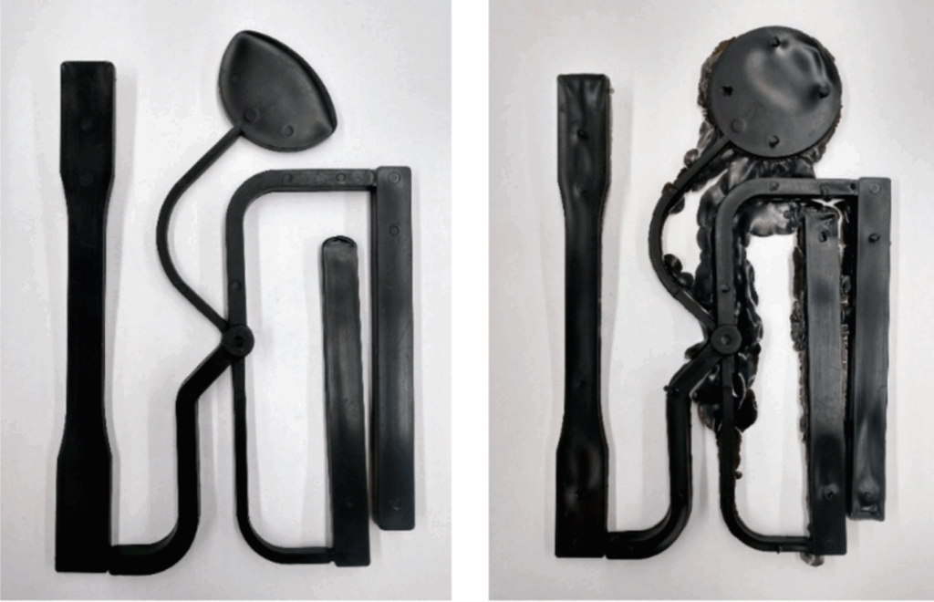
#7 Burn marks
Scorch marks are a process-related injection molding defect characterized by yellow, brown, rust, or black discoloration on the surface of the part—usually at the end of flow paths or in areas of air retention. Although mainly considered a visual defect, in more severe cases they may indicate localized overheating, leading to polymer degradation and even reduced structural strength in the affected area.
Design improvements:
- Poor exhaust causing air retention: Improve the vent groove or add vent holes to safely discharge gas before the resin enters the cavity.
- Excessive injection speed or pressure: Appropriately reduce injection speed and pressure to prevent air from being rapidly compressed and causing overheating and combustion.
- Excessive melt or mold temperature: Lower the melt temperature or optimize the molding cycle to prevent polymer degradation in air-trapped areas.
- Contaminants or degradable materials inside the mold: Clean the mold surface and avoid using degraded resin to prevent residue carbonization that may cause burn-like marks.
- Unreasonable runner or gate design: Redesign runners and gates to ensure smooth resin flow and reduce the risk of air retention in dead corners.
Manufacturing precautions:
If scorch marks repeatedly appear in the same area of the part, consider rearranging the gate or adjusting the flow path to prevent air retention in that area. Such simple design adjustments can significantly reduce local heat buildup, effectively eliminating surface discoloration caused by burning.
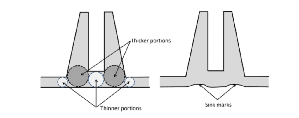
#8 Shrinkage marks
Shrinkage marks are small depressions or shallow pits appearing on the surface of parts, usually in thicker areas or near ribs and columns. This occurs because the outer layer of the part cools and solidifies faster than the inside, causing the interior to continue shrinking and pulling the surface inward, thus forming defects.
Design Modification:
- In thick-walled areas, reduce wall thickness as much as possible to promote uniform cooling.
- Follow reasonable design principles for ribs and bosses: rib thickness should not exceed 50–70% of the thickness of adjacent walls.
- Avoid overlaying thick features in the same area (such as placing bosses on the ribs) unless absolutely necessary.
- A hollowed-out design removes excess material from thick cross-sections while maintaining strength without compromising strength.
- Collaborate with manufacturers to optimize gate positions to ensure sufficient pressure retention in key areas.
- Materials such as ABS, polycarbonate (PC), and PMMA (acrylic acid) are selected.
Points to note during the manufacturing process:
- Insufficient cooling time or uneven mold temperature can cause internal shrinkage.
- Localized areas where materials are too thick can accumulate heat, causing delayed curing.
- If the injection pressure or holding pressure is too low, the ability to compensate for shrinkage is reduced.
- Semi-crystalline plastics (such as PA, POM, PP) have a higher shrinkage rate and are more prone to shrinkage marks.
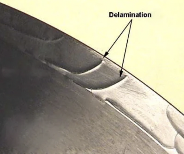
#9 Surface delamination
Surface delamination manifests as flaking or flake delamination defects, usually caused by contaminants or incompatible materials, which hinder the normal bonding between plastic layers.
Design Modification:
- Avoid combining incompatible resins or performing secondary injection molding on incompatible materials.
- Try to use a single material design unless secondary injection molding has proven good compatibility.
- Minimize the use of release agents that may affect bonding.
- Before making prototypes, confirm the compatibility of materials with the supplier.
Points to note during manufacturing:
- Thoroughly dry the moisture-absorbing material.
- When replacing materials, perform discharge and cleaning of the equipment.
- Keep hoppers, nozzles, and barrels clean to prevent contamination.
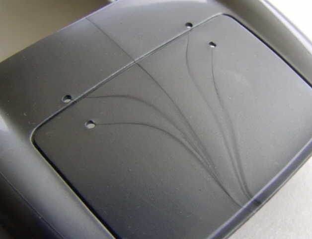
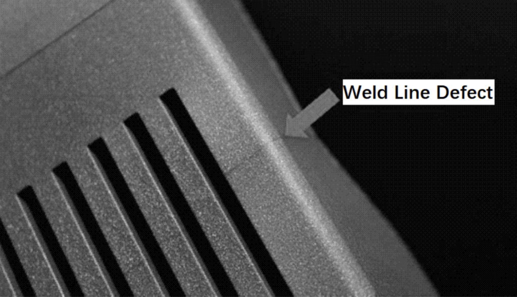
#10 Weld marks (bonding lines).
Weld marks form when the front edges of two molten plastics meet but do not fully fuse, manifesting as visible seams or structural weaknesses.
This defect is especially common in parts with complex geometric structures, multiple gates, or components that interfere with plastic flow characteristics such as holes, bosses, or ribs.
Design Modification:
- Reducing the number of melt flow fronts: Simplifying part geometry and reducing obstruction to melt flow.
- Gate Position Optimization: Gate placement ensures the melt convergence is away from high-stress areas.
- Enhance local strength: Place reinforcing ribs or bosses near the weld marks to improve mechanical strength.
- Avoid unnecessary shunting: minimize holes, inserts, or abrupt geometric changes to prevent forced shunting of the melt.
Points to note during the manufacturing process:
- Increasing mold and melt temperature: Improves the bonding quality of the melt forward.
- Adjusting injection speed: Delays melt curing in the confluence zone, promoting a stronger fusion.
Improved exhaust design around welding line positions.
Pro tip: For load-bearing or high-stress components, rearrange the gate or redesign the part to shift the welding line to non-critical load-bearing areas to improve overall structural reliability.
#11 Warping
Warpage refers to visible bending, twisting, or deformation of molded parts. When different areas of the part are cooled and contracted unevenly, internal stress is generated, leading to shape distortion.
Design Modification:
- Maintain uniform wall thickness throughout the design to ensure consistent cooling.
- Avoid large, flat, rib-free or curved structures, as these areas are more prone to deformation.
- Structural supports such as ribs are added to maintain lightweight design while reducing warping.
- Choose low-shrinkage materials (such as filler resins) to achieve better dimensional stability.
- Reduces the sharp transition between thick-walled and thin-walled areas, avoiding deformation caused by differences in cooling rates.
Manufacturing precautions:
- Balance the layout of cooling channels within the mold.
- Uses temperature-controlled mold circuits to reduce cooling rate differences.
- Lower mold temperature and increase holding pressure when applicable.
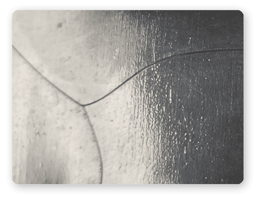
#12 Radiation
Shot lines occur when high-speed molten plastic flows into the mold cavity rapidly cool before fully blending with the surrounding material, forming serpentine surface defects.
This defect not only affects the appearance of molded parts but may also cause weak strength zones locally due to incomplete interlayer bonding of the material.
Design Modification:
- Use lap gates or fan-shaped gates to reduce the flow rate of melt entering the cavity.
- Maintain smooth transitions at wall thickness transitions to avoid sharp corners.
- Progressive rounded corners are used at the entrance to reduce abrupt wall thickness changes.
- Reduce the initial filling speed during the prototype phase to evaluate melt flow behavior.
Points to note during manufacturing:
- Reduce injection speed at the beginning of the injection cycle.
- Increase the mold temperature to promote better melt fusion.
- Optimize gate size to reduce direct melt impact on the cavity surface.
#13 Vacuum Hollow
Vacuum cavities refer to air layers present inside parts. Although not necessarily visible to the naked eye, they may weaken the structural strength of the part.
Design Modification:
- Avoid thick solid cross-sections and use hollowed-out structures whenever possible.
- Add openings or internal channels in thick cross-sections to reduce material buildup.
- Design exhaust ducts in areas where air may stagnate.
- If internal cavities are critical to performance, micro-CT inspection or sampling and cutting can be used.
Manufacturing precautions:
- Improve mold venting design, and use gas-assisted injection molding processes when necessary.
- Adjust holding pressure and duration to eliminate stagnant air.
- A lower injection speed is used to allow sufficient time for air to be expelled.
#14 Color change
Discoloration refers to defects where the color of the part is uneven, spotted, or does not match the expected color. Common causes include moisture from raw materials, thermal degradation, poor dispersion of masterbatch, or contamination caused by residual impurities from the machine.
Design Modification:
- Uses stable, proven colorants with high heat resistance.
- Avoid parts in the design that require frequent color changes.
- Clearly indicate the RAL or Pantone color code and masterbatch ratio in the documentation.
- Reduce complex areas where multiple material combinations are used in critical areas, enabling better control over color consistency.
Manufacturing Precautions:
- Maintain an appropriate barrel temperature distribution.
- Thoroughly clean the screw and barrel between batches of different colors.
- Use appropriate metering equipment to add masterbatches or colorants to ensure accurate proportions.
#15 Jet Pattern (Silver Pattern)
Jet patterns appear as silver streaks on the surface of the part, usually near the gate. Its main causes are moisture and contaminants in the resin, or excessive shearing.
Design Suggestions:
- Avoid sudden transitions or sharp edges near the gate.
- Increase exhaust space in the gate area to release moisture.
- Choose low-hygroscopic materials or add drying steps during supply and processing.
Manufacturing precautions:
- Pre-dried hygroscopic materials such as PA, PC, and ABS.
- Reduce injection speed to minimize shear.
- Regularly clean the hopper and dryer filters.
#16: Pollution
Contamination refers to foreign matter mixing into molten materials during processing. Such defects typically manifest as black spots, streaks, or abnormal inclusions on the part surface—in some cases, they may also affect the strength or dimensional stability of the part.
Contaminants typically enter the processing through improper material handling, improper maintenance of molds and equipment, or debris generated by wear.
Design Modification:
- Avoid unnecessary material changes or color changes unless absolutely necessary.
- Limit deep ribs or narrow features to prevent pollutants from retaining or accumulating.
- Increase draft angles for internal features to improve melt flow and material washing.
- Use consistent resin for the same series of parts, reducing cleaning cycles and discharge times.
- In designs with strict tolerance or appearance requirements, internal quality control measures (such as material batch traceability) are used.
Manufacturing precautions:
- Perform regular equipment maintenance to detect and repair mold wear.
- Maintain a clean and oil-free production environment to reduce the risk of airborne pollutants.
- Regularly clean the hopper, barrel, and screw assembly to prevent material accumulation.
- Store the resin in sealed, dry containers to avoid dust and moisture from the air.
- Thoroughly discharge between different resins or colorants to prevent cross-contamination.
Injection molding defects classified by severity and cost impact
| Types of defects | Structural impact | Appearance impact | Production risk | Typical cost increases |
|---|---|---|---|---|
| Short Shots | High | Middle | High | ↑↑ (Parts scrapped) |
| Flash (Flash) | Low | Middle | Low | → (edges trimmed) |
| Improper Parting Line Placement | Middle | Middle | Middle | ↑(Mold rework) |
| Bubbles & Voids | Middle | Middle | Middle | ↑ (Mold/Process Adjustment) |
| Gate Vestige | Low | Middle | Low | → (Surface Finishing/Gate Adjustment) |
| Flow Lines | Low | High | Low | → (Process Adjustment) |
| Burn Marks | Middle | High | Middle | ↑ (Process adjustment) |
| Sink Marks | Middle | High | Middle | ↑ (Mold redesign) |
| Delamination | High | Middle | High | ↑↑ |
| Weld Lines | Middle | Middle | Middle | → |
| Warping | High | High | High | ↑↑ (Rework or scrapping) |
| Jetting | Middle | High | Middle | ↑ |
| Vacuum Voids | High | Low | Middle | ↑ (Mold redesign) |
| Discoloration | Low | High | Low | → |
| Splay Marks | Low | High | Low | → (Drying/Parameter Adjustment) |
Avoiding injection molding defects depends not only on technical precision and design level, but also on choosing a partner who can anticipate and prevent problems before they occur.