In the modern world of CNC machining, manufacturing typically starts with a 3D CAD model created using a CAD 3D modelling software. Using CAM software, the 3D model is then converted to G-code, a machine language that CNC machines understand, and the machine produces the part from a block of material. A 3D CAD file carries the major details that the CNC machine requires to create a part.
This makes it possible for you to upload a 3D model on our Instant Quoting Engine and receive a quote in seconds. However, in many cases, a 3D CAD file does not completely eliminate the need for technical drawings.
Technical drawings are documents that contain detailed 2D drawings of a part to be manufactured, along with various crucial manufacturing data. These documents ensure the clear and complete communication of the technical requirements of projects between the designer and the machinist.
In many cases, a machinist can manually produce a part, working with only a technical drawing. In CNC machining, technical drawings are crucial accompaniments of 3D models. In this guide, we will explore the importance of technical drawings and the things that are included in these drawings. We will then go through the step-by-step process of creating a perfect technical drawing.
Why are technical drawings important?
As earlier stated, in CNC machining, technical drawings are accompaniments of 3D CAD files. Some of the vital roles they play are as follows.
- They depict features, such as internal and external threads that cannot be adequately conveyed in a 3D CAD model
- Through dimensions, tolerances, and annotations, they enable the machinist to have a complete understanding of the part to be created
- They contain critical details such as tolerances that exceed standard tolerances
- They enable the designer to communicate certain requirements, such as finishing and surface roughness, to the machinist
Even if your design doesn't have any special features or requirements, it is recommended that you accompany your 3D model with a technical drawing, as this will be used as a reference throughout the different stages of manufacturing.
Furthermore, these documents give a clear and absolute view of parts, making it easy for a machinist to interpret a part's geometry and identify its primary dimensions, functions, and crucial features. They also make cost estimation easier. Technical drawings are compulsory when your part features threads, tolerances, or different surfaces finish on different areas.
What makes up a technical drawing?
Technical drawings typically comprise the following, coordinates, a title block, orthographic views of the part, section views, detail views, and notes to the manufacturer.
Title block
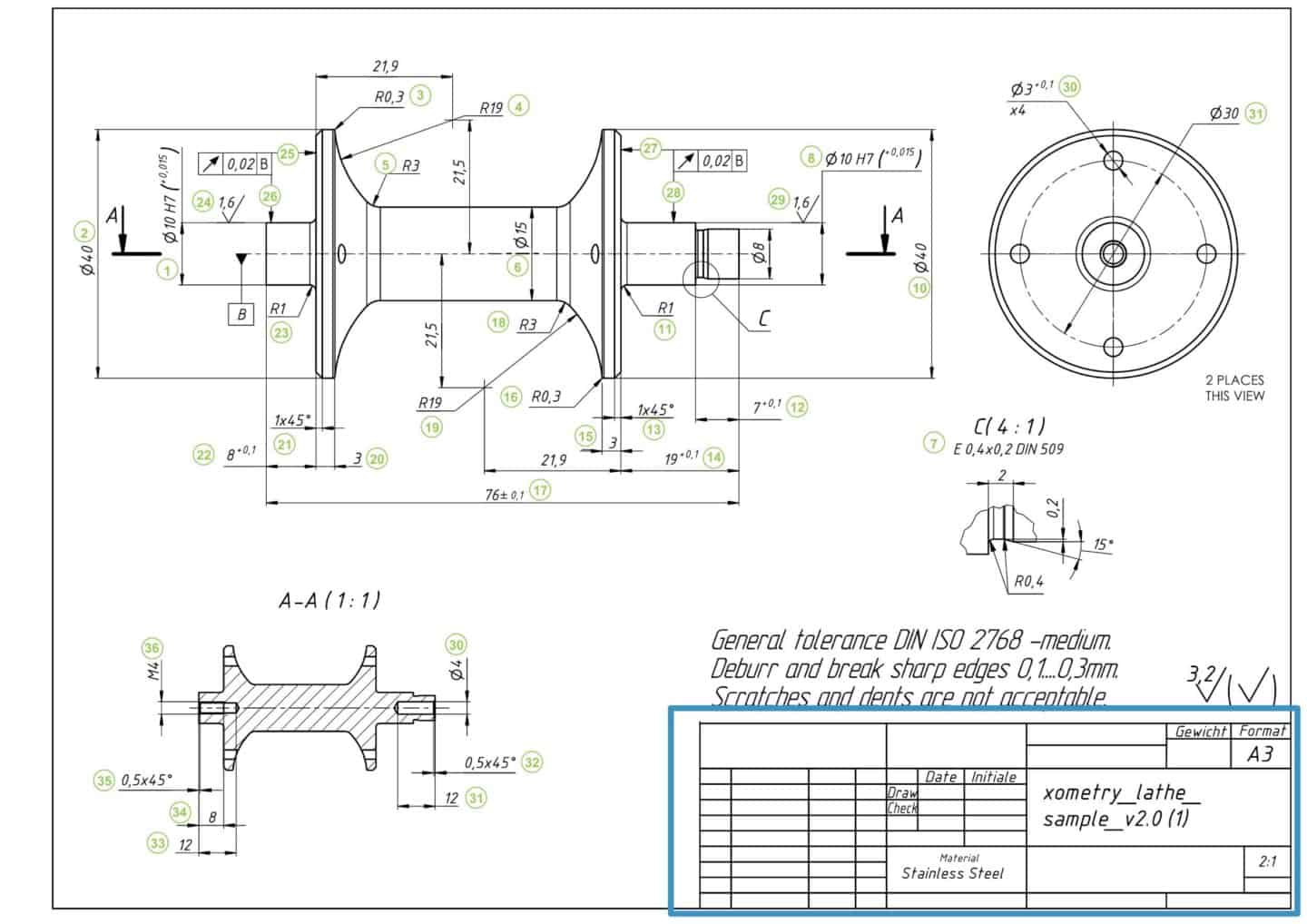
The title block is located at the bottom right corner of the document. It contains basic information about the part, including the part name, names of the people that worked on the part (design, checking, and approval), the name of the company, etc. It also contains technical information such as the system of measurement, angle of projection, surface finish requirements, scale, and material. The title block's template (size and content) may be a standard or may be custom.
Coordinates
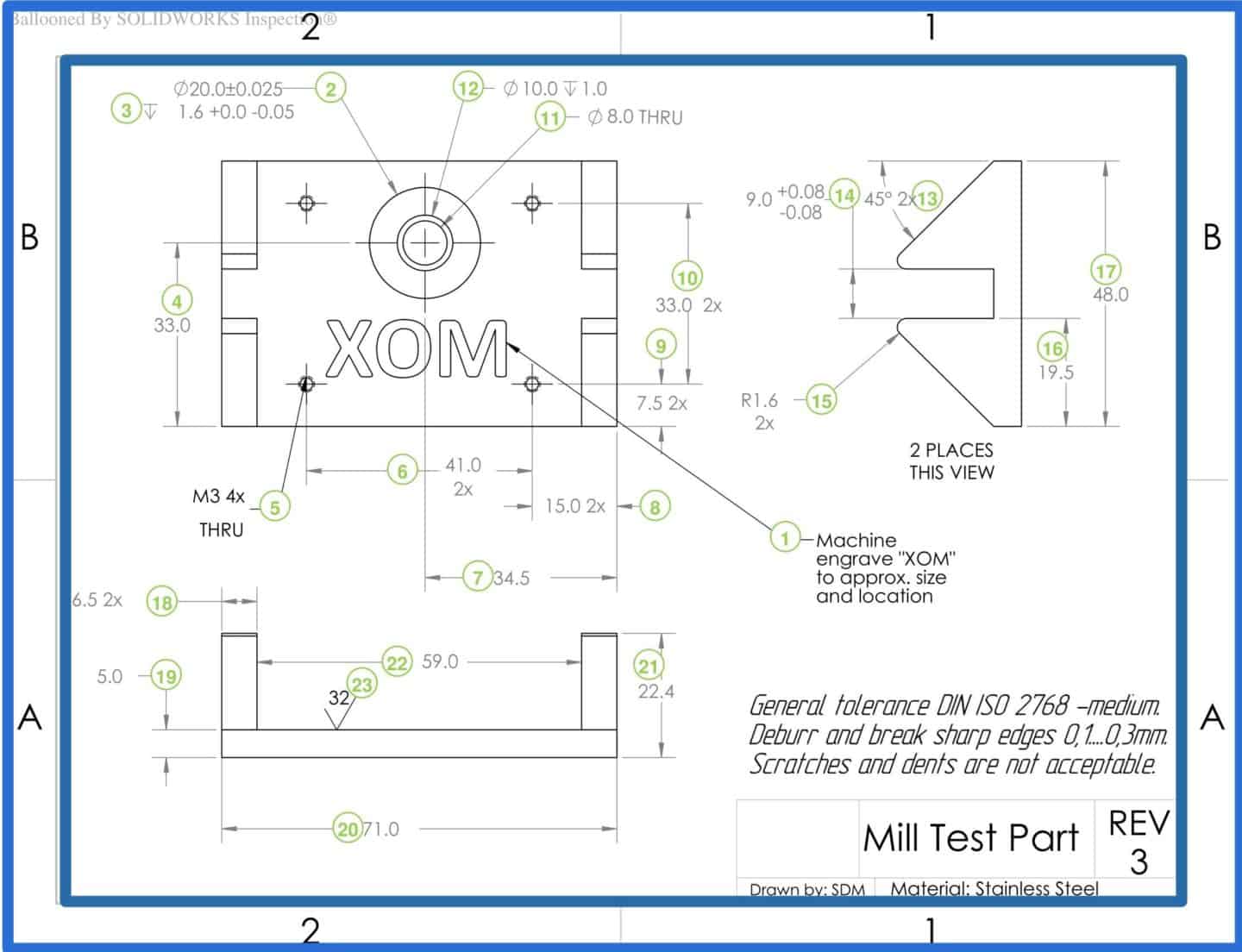
Coordinates are usually used in big or complex technical drawings and are placed along the borders of the drawing. They serve as reference points when discussing the contents of the drawing.
Orthographic views
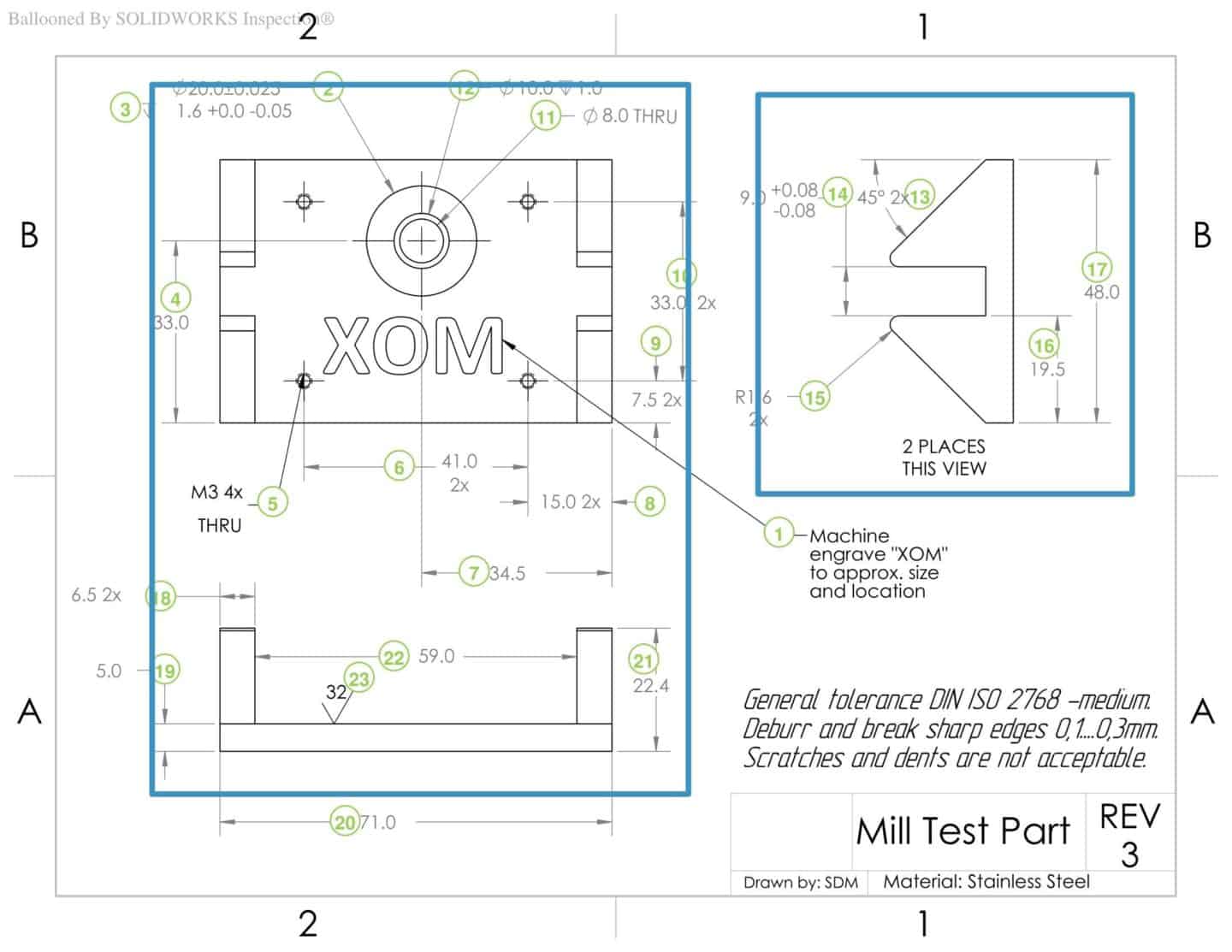
The orthographic views convey the most important information about a part's geometry. These views carry the majority of the dimensions and tolerances. They are 2D representations of a 3D object, obtained from various points of view, typically the front, plan, and end.
Hidden lines may be included in orthographic views to depict essential features that are not visible. In most cases, two to three orthographic views are enough to correctly describe the entire geometry of a part.
Isometric view
The isometric view is a 3D pictorial representation of the part. While it's not always necessary, it is a good practice to include the isometric view in a technical drawing as it makes it easier for the machinist to understand the part geometry. In addition to providing more details about a part, the isometric view may also provide information such as installation direction and build orientation.
Section view
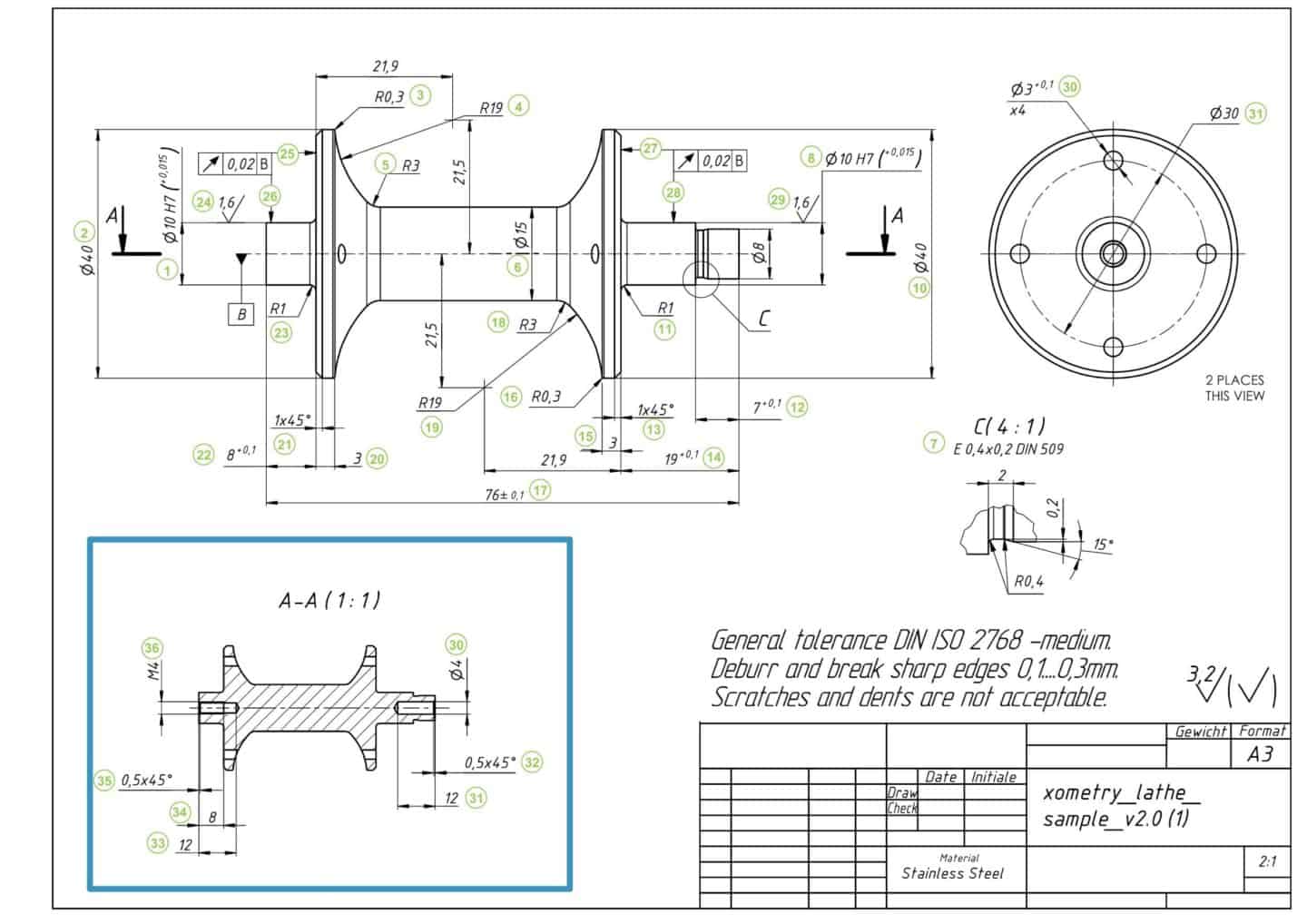
The section view is a 2D depiction of the part when it's cut through. Section views are used to show the internal features of a part that are not visible in both the isometric and orthographic views. They are usually positioned in line with an orthographic view.
A labelled cutting line in the orthographic view showing where the part is cross-sectioned to provide the section view and the direction of the cut. Section views are characterised by their crosshatch patterns which indicate areas where the material was cut away. Complex parts may feature several section views.
Detail views
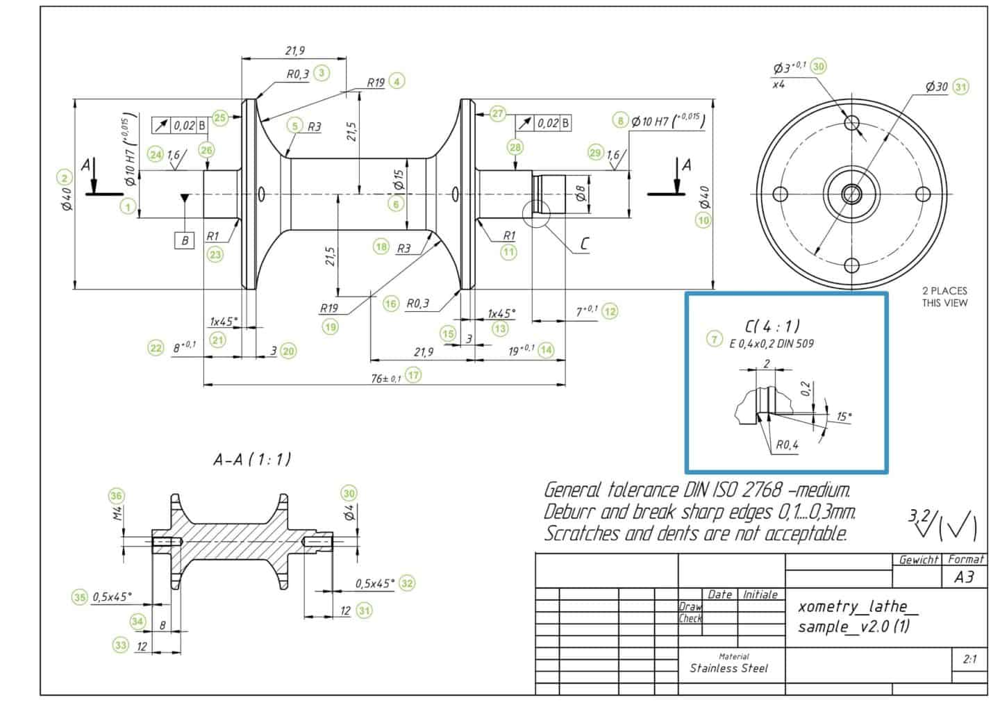
When the orthographic view features complex and difficult to dimension areas, detailed views are used to highlight such areas. Detailed views don't have to be the same size or placed in line with the orthographic views and can be placed anywhere in the drawing. Detailed reviews are labelled with a single letter that shows what area of the orthographic view is being detailed.
Note to the manufacturer
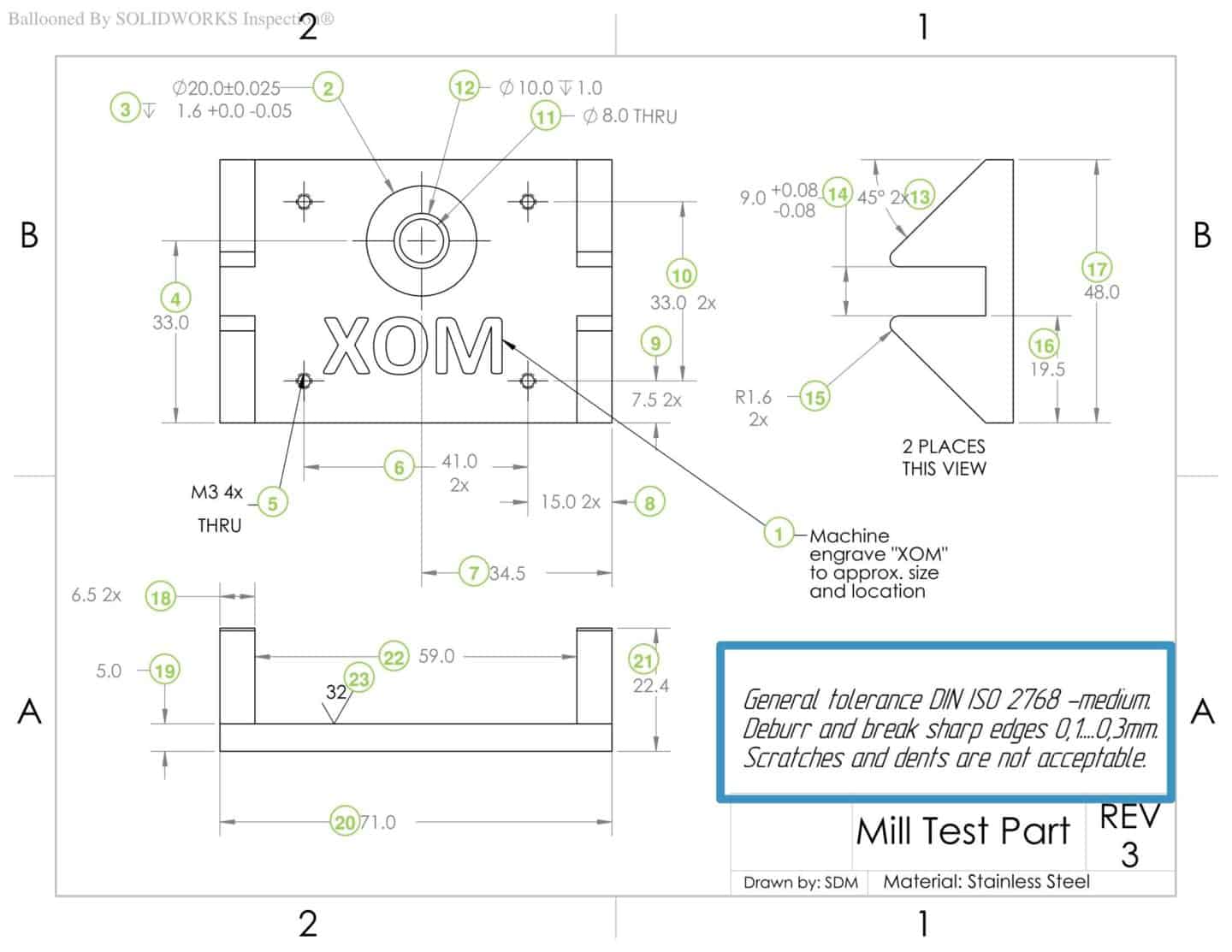
The notes to the manufacturer are usually located at the bottom left of the technical drawing but may also be placed above the title block. It contains any additional information that isn't included in the drawing, as well as instructions for the machinist. For example, notes may include instructions to break and deburr all sharp edges, surface finish requirements, other components to be assembled with the part, etc.
Clear communication is most important
Note that there are no hard set, absolutely compulsory techniques for creating technical drawings. There are various standards and best practices involved. Therefore, as long as all the technical requirements are clearly communicated and your drawing can be interpreted by machinists, your drafting techniques aren't of immense importance. For example, it's recommended but not compulsory to fully dimension every aspect of your drawing as basic dimensions are already contained in the 3D CAD file. Instead, you can save time by annotating only crucial features that require measurement by the machinist.
10 steps to prepare a perfect technical drawing and what to include in it
As stated earlier, modern manufacturing begins with a 3D CAD model. Most 3D CAD software have an interface for technical drawing that allows you to very easily create a technical drawing based on an existing card model. This interface usually features all you need to create views and annotate, dimension, and apply tolerance to your drawing, eliminating the need to design the views from scratch.
There are also software programs that enable you to create technical drawings without a 3D model.
The following are the steps you need to take, together with some tips, to prepare the perfect technical drawing.
Step 1. Select your template
There are standard ASTM, DIN, and ISO templates that specify the coordinates, angle of protection, and title block characteristics. You can also create a custom template, but take note to include all the necessary details in the title block.
Step 2. Place your orthographic views, centring them as much as possible
Remember to leave sufficient space between them to add dimensions. Avoid excessive use of hidden lines as these can make the drawing confusing and disorganised.
Step 3. Add detail and/or section views accordingly
If the part is highly complex, has hidden features, or has difficult to dimension areas.
Step 4. Add the isometric view
The isometric view isn't always necessary but should be included whenever there is space and if the part geometry is too complex to easily interpret from only the orthographic views.
Step 5. Place construction lines
Such as centerlines, centre marks, and cutting lines on all the views.
Step 6. Add dimensions to your drawings
Focus on the vital dimensions on the orthographic and detail views. Ensure that all the dimension lines and figures are clearly visible and do not cross each other or the drawing. The image below shows dimensions placed on the orthographic, detail, and section views. The dimensions are numbered for identification.
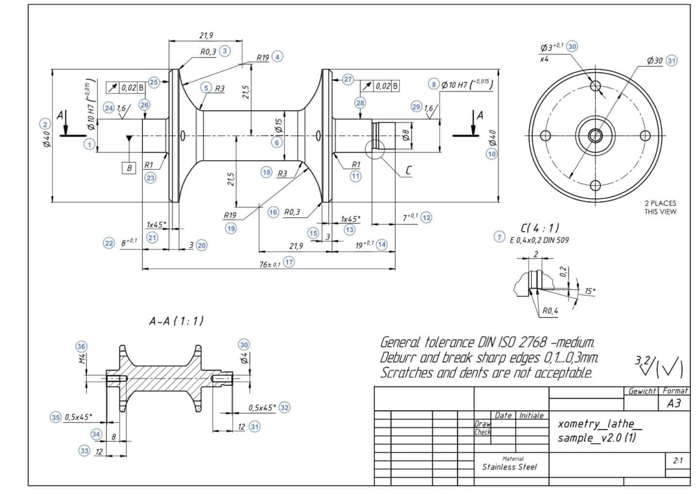
Dimensions are very important aspects of a technical drawing. Where a customer does not specify dimensions, it is assumed that size has been left to the discretion of Xometry's experts, who, while guaranteed to deliver high-quality parts, would not be held accountable for any size discrepancy claims made by the customer. That said, the following are some tips to help you dimension your technical drawing properly:
- Begin by adding overall dimensions before adding dimensions that are critical for the part's end use. Next, add dimensions to all other features.
- Try to add all dimensions on a view from a common baseline.
- When a feature is visible in more than one view, there's no need to dimension it on all views. Instead, add dimensions on the view that most clearly describes the feature.
- When there are multiple identical features, add dimensions to only one of them, indicating the number of times the feature appears in the current view. For example, if there are three identical holes of 2 mm in diameter visible on the plan orthographic view of a part, add the following dimension to one of the holes - 3 x ø2.0.
Step 7. Specify the location, length and size of all holes and thread
We recommend using standard-sized holes in your design as these can easily be drilled in after machining. Numbers 5 and 12 in the image below specify a thread and a hole, respectively.
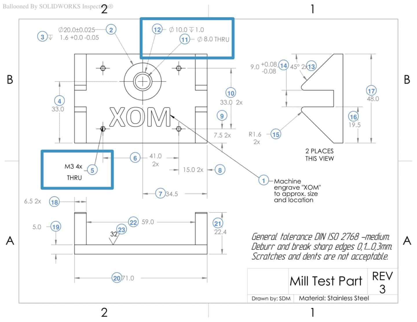
Holes may include counterbores or countersinks. Dimensioning all the aspects of a hole is tedious, and so call outs are used instead. A typical hole callout specifies the hole depth and diameter, the number of identical holes, and the presence of a counterbore or countersinks, along with the depth of these features. Threads should also be of standard thread sizes and also need to be specified.
Step 8. Add tolerances to critical features
For the features that require higher tolerances than those defined by the ISO-2768 medium tolerance standard. By default, Xometry Europe applies tolerances based on this tolerance standard unless higher tolerances are specified. Similar to dimensions, tolerances play a vital role in the end use of a part and should be very carefully applied.
Tolerances specify a range of acceptable deviations from the values of a dimension. There are various types of tolerances that may be applied to a technical drawing. These include bilateral tolerances, unilateral tolerances, interference tolerances, and geometric dimensioning and tolerancing (GD&T).
Step 9. Fill the title block
Make sure that all basic and technical details are included.
Step 10. Include all notes and additional instructions to the manufacturer
After creating it, export the finished technical drawing in the PDF file format to be uploaded during your order placement on our Instant Quoting Engine.
Conclusion
At Xometry Asia, we recommend including technical drawings together with your 3D model once you place an order, as this makes it easier for us to perfectly execute your project and deliver high-quality parts. Now that you've learned how to prepare the perfect technical drawing, visit our quoting platform to upload your models and technical drawings and begin your journey to fast, stress-free, and efficient manufacturing.