The top 6 mistakes CAD designers make when designing for CNC and how to avoid them. By taking note of these, it’s unlikely that you’ll need to return to the design table, thereby saving cost, time and resources.
CNC machines provide engineers and machinists with one of the easiest ways of creating metal and polymer parts. However, creating CAD designs for CNC machines can be rather problematic. It requires maximum concentration and vigilance to avoid faulty, inaccurate, or expensive parts production. Below are the top 6 mistakes in CAD designs for CNC machining.
Designing excessively thin walls
Designers often fail to consider the possible behaviour of a workpiece during machining. The work piece’s properties are another important consideration; designing excessively thin walls in one of the consequences of these oversights.
For example, thin walls machined from low-stiffness aluminium may snap off or distort during a milling process as a result of excessive vibration. Reducing the wall thickness decreases the stiffness of the material, thereby increasing vibrations during machining and lowering the attainable accuracy. One way to overcome this problem is by maintaining low wall height to thickness (H:T) and Wall height to Length (H:L) ratios when designing a thin-walled section. An unofficial industry standard minimum wall thickness is 0.794mm.
However, thin walls are very often a design requirement. In such cases, it is more economical to employ other manufacturing processes such as sheet metal fabrication.
Designing features that are impossible to machine
Not all features designable on a CAD package can be efficiently machined by a CNC machine. One of such features to be avoided when designing for CNC machining is curved holes. No matter the degrees of freedom that can be achieved by a CNC machine, it cannot effectively machine a curved hole.
If this feature is necessary for your part then a method known as electrical discharge machining (EDM) may be used. EDM is a process in which the desired shape is created using electrical discharge.
Excessive use of tolerances
Tolerances define the boundaries for an acceptable dimension. It varies between machines. Many CAD designers design for CNC machining without a general knowledge of the tolerance of the machine for which they are designing. This reduces the quality of the machined part. It is crucial to remove unnecessary tolerances from a design in accordance with the characteristics of the machine being used.
Even for high-quality CNC machines, excessive tight tolerances in your design can be expensive. Not all surfaces of a part require tolerancing. Avoid assigning numeric callouts such as radii and diameter, to such surfaces in your design.
Designing unnecessary aesthetic features
In order to save cost and time when designing for CNC machining, it’s necessary to consider the amount of material to be removed and the process to be used in doing this. Questions like “is it necessary to remove material for just looks?” and “is it entirely necessary to add a single complex feature, which requires 5-axis machining to the design?” should be considered by a designer when designing for CNC machining.
Unnecessary removal of material and consideration of aesthetic should be avoided. Instead of machining to achieve aesthetics, post-machining processes such as electro-polishing may be used.
Designing too deep cavities
CNC tools have a limited cutting length. Milling tools are typically most efficient when milling cavities double or triple their diameter in depth. For example, a ø15mm milling tool safely cut cavities up to 35 mm deep. Deep cavity milling may cause inability of the tool to reach the surface to be milled; tool deflection caused by the excess overhang of a tool from its clamp; tool fracture; and difficulty in chip evacuation. To overcome these challenges, you have to do the following:
- Progressively step down the end mill in smaller and smaller increments.
- Use a sufficiently sized cutting tool or use an extended reach tool holder. This solves the problems of tools reach and tool deflection.
- Deliver the employed coolant at high pressure in order to effectively evacuate machine chips.
- Use other forms of machining such as EDM.
Designing internal angles without radii
CNC milling tools are cylindrical in shape. As a result of this, these tools always create a radius when milling internal vertical edges. It is a common mistake when designing for CNC machining to design sharp edges for internal angles. Since the machine is going to create a radius automatically, it is best to include it in your design in the first place.
When designing deep rectangular pockets, ensure that your add a corner radius of at least ⅓ of the pocket’s depth. Sharp edges or insufficiently large corner radii require much smaller diameter tools at lower speeds, thereby increasing machining cost and time.
Also, the radius of the tool to be used in machining should be considered when designing a corner radius. The corner radius should be a bit larger than the radius of the milling tool. This allows the tool to cut at faster speeds and also reduces the stress on the tool.
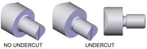
If your design requires sharp edged internal angles, such as cavities in which a rectangular-shaped part needs to fit, the it best to design the cavity with undercuts.